Private Pilot · Unit 6 · 30 min
Airport Lighting and Wake Turbulence
By the end of this lesson you will know:
- which color combination a beacon flashes for a lighted land airport, and what a beacon lit in daylight often indicates inside a surface area
- the red and white combinations a two-bar VASI and a four-unit PAPI show for above, on, and below the glidepath
- the color of every runway and taxiway light, including the caution zone and the two colors an end light emits
- how many microphone clicks turn pilot-controlled lighting on, at what intensity, and for how long
- which configuration, weight, and speed produce the strongest wake vortices, and how far and how fast a vortex sinks and drifts
- where to fly and where to touch down when you land or depart behind a larger aircraft
The airport at night
The majority of airports have some type of lighting for night operations. The variety and type of lighting systems depends on the volume and complexity of operations at a given airport. Airport lighting is standardized so that airports use the same light colors for runways and taxiways (PHAK Chapter 14).
The Chart Supplement U.S. entries reproduced in the traffic pattern lesson print REIL and PAPI on their runway lines. This lesson covers the equipment those abbreviations name, together with the wake turbulence that other aircraft leave behind at the same airport.
PHAK Ch 14, "Airport Lighting"
The airport beacon
An airport beacon helps a pilot identify an airport at night. Beacons are normally operated from dusk until dawn (PHAK Chapter 14). A beacon may be an omnidirectional capacitor-discharge device, or it may rotate at a constant speed, which produces the visual effect of flashes at regular intervals (AIM 2-1-9).
The beacon has a vertical light distribution that makes it most effective from 1 to 10 degrees above the horizon, although it can be seen well above and below that spread (PHAK Chapter 14; AIM 2-1-9).
The combination of light colors from an airport beacon indicates the type of airport (PHAK Chapter 14):
- White and green: The beacon flashes white and green at a lighted land airport.
- White and yellow: The beacon flashes white and yellow at a lighted water airport.
- Green alone is used only in connection with a white-and-green display, and yellow alone only in connection with a white-and-yellow display (AIM 2-1-9).
- Two quick white flashes between the green flashes distinguish a military airport beacon from a civil one. A military beacon otherwise flashes alternately white and green (AIM 2-1-9).
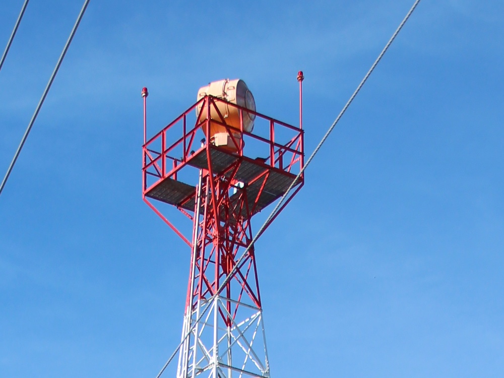
In Class B, Class C, Class D, and Class E surface areas, operation of the airport beacon during the hours of daylight often indicates that the ground visibility is less than 3 miles, or that the ceiling is less than 1,000 feet, or both (AIM 2-1-9). Those are the two conditions the weather minimums lesson attached to a surface area under 14 CFR 91.155(c) and 91.155(d).
There is no regulatory requirement for daylight operation, and it is the pilot's responsibility to comply with proper preflight planning as required by 14 CFR 91.103 (AIM 2-1-9). Pilots should not rely solely on the operation of the airport beacon to indicate if weather conditions are IFR or VFR (AIM 2-1-9). At many airports a photoelectric cell or a time clock turns the beacon on, and air traffic control (ATC) personnel cannot control it (AIM 2-1-9).
PHAK Ch 14, "Airport Beacon"; AIM 2-1-9; 14 CFR 91.103, 91.155(c), 91.155(d)
Approach light systems
Approach light systems provide the basic means to transition from instrument flight to visual flight for landing (AIM 2-1-1). They are a configuration of signal lights starting at the landing threshold and extending into the approach area a distance of 2,400 to 3,000 feet for precision instrument runways and 1,400 to 1,500 feet for nonprecision instrument runways (AIM 2-1-1). Some systems include sequenced flashing lights which appear to the pilot as a ball of light traveling towards the runway at high speed, twice a second (AIM 2-1-1). Approach lights can also aid pilots operating under VFR at night (PHAK Chapter 14).
AIM 2-1-1; PHAK Ch 14, "Approach Light Systems"
The visual approach slope indicator
A visual glideslope indicator provides the pilot with glidepath information that can be used for day or night approaches. By maintaining the proper glidepath as provided by the system, a pilot should have adequate obstacle clearance and should touch down within a specified portion of the runway (PHAK Chapter 14).
The visual approach slope indicator (VASI) is the most common of these systems in use (PHAK Chapter 14). It consists of light units arranged in bars. A two-bar VASI has a near light bar and a far light bar, and it provides one visual glidepath, normally set at 3 degrees (PHAK Chapter 14). A three-bar VASI adds a middle bar and provides a second, higher glidepath intended for use only by high cockpit aircraft (AIM 2-1-2).
Each light unit projects a beam of light with a white segment in the upper part of the beam and a red segment in the lower part (PHAK Chapter 14). A bar therefore shows white to an airplane above the boundary between the two segments and red to an airplane below it. The far bar's boundary is set higher than the near bar's, which divides the approach airspace into three bands.
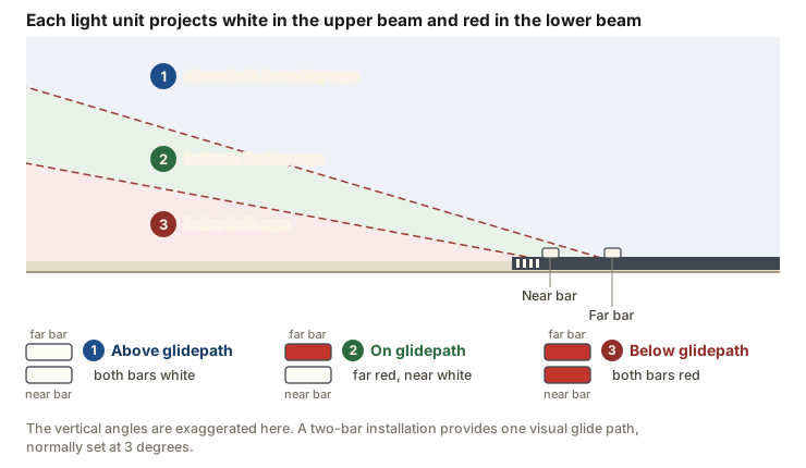
The three indications follow from that geometry. Both bars white means you are above the glidepath. The far bar red over the near bar white means you are on the glidepath. Both bars red means you are below the glidepath (PHAK Figure 14-29).
VASI lights are visible from 3 to 5 miles during the day and up to 20 miles or more at night (AIM 2-1-2). The visual glide path provides safe obstruction clearance within plus or minus 10 degrees of the extended runway centerline and to 4 nautical miles from the runway threshold (AIM 2-1-2). Lateral course guidance comes from the runway or the runway lights, so descent using the VASI should not be initiated until the aircraft is visually aligned with the runway (AIM 2-1-2).
Under 14 CFR 91.129(e)(3), each pilot operating an airplane approaching to land on a runway served by a visual approach slope indicator must maintain an altitude at or above the glide path until a lower altitude is necessary for a safe landing. Paragraph 91.129(e)(4) provides that this does not prohibit normal bracketing maneuvers above or below the glide path that are conducted for the purpose of remaining on the glide path. Section 91.129 governs operations in Class D airspace, and it is extended to Class C airspace by 14 CFR 91.130(a) and to Class B airspace by 14 CFR 91.131(a).
PHAK Ch 14, "Visual Glideslope Indicators" and "Visual Approach Slope Indicator (VASI)"; AIM 2-1-2; 14 CFR 91.129(e)(3), 91.129(e)(4), 91.130(a), 91.131(a)
The precision approach path indicator
The precision approach path indicator (PAPI) uses light units similar to the VASI, but they are installed in a single row of either two or four light units (AIM 2-1-2). The row is normally installed on the left side of the runway (AIM 2-1-2). The visual glide path typically provides safe obstruction clearance within plus or minus 10 degrees of the extended runway centerline and to 3.4 nautical miles from the runway threshold (AIM 2-1-2).
Each unit in the row is set to a different angle, and the unit nearest the runway carries the highest one. On a descent through the glidepath the units therefore change from white to red one at a time, starting with the unit nearest the runway (PHAK Figure 14-30).
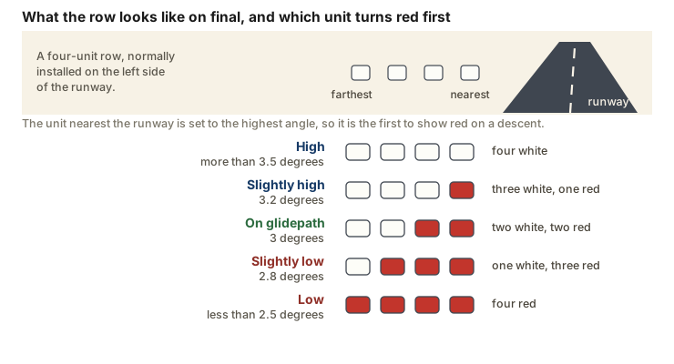
For a typical 3 degree glide slope, a four-unit row reads as follows (PHAK Figure 14-30):
- Four white: high, more than 3.5 degrees.
- Three white and one red: slightly high, 3.2 degrees.
- Two white and two red: on the glidepath, 3 degrees.
- One white and three red: slightly low, 2.8 degrees.
- Four red: low, less than 2.5 degrees.
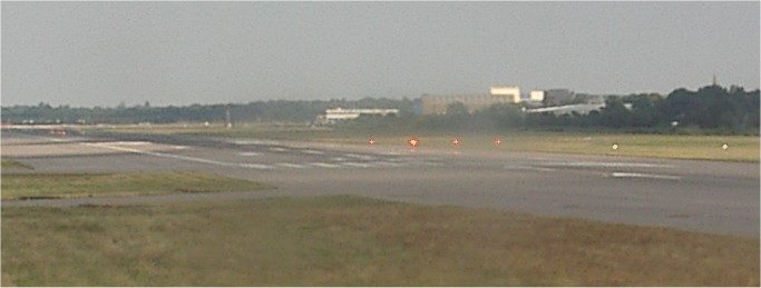
AIM 2-1-2; PHAK Ch 14, "Other Glidepath Systems" and Figure 14-30
Tri-color and pulsating systems
A tri-color system consists of a single light unit projecting a three-color visual approach path. Below the glidepath is indicated by red, on the glidepath by green, and above the glidepath by amber (PHAK Chapter 14). When descending from green to red, the pilot may see a small area of dark amber, and pilots should not mistake this area for an above the glidepath indication (PHAK Chapter 14; AIM 2-1-2). The useful range is approximately one-half to one mile during the day and up to five miles at night (AIM 2-1-2).
A pulsating system normally consists of a single light unit projecting a two-color visual approach path. The on glidepath indication is a steady white light, the slightly below glidepath indication is a steady red light, and the above glidepath indication is a pulsating white light (PHAK Chapter 14). If the aircraft descends further below the glidepath, the red light starts to pulsate, and the pulsating rate increases as the aircraft gets further above or below the desired glideslope (PHAK Chapter 14). The useful range is about four miles during the day and up to ten miles at night (PHAK Chapter 14).
PHAK Ch 14, "Other Glidepath Systems"; AIM 2-1-2
Runway lighting
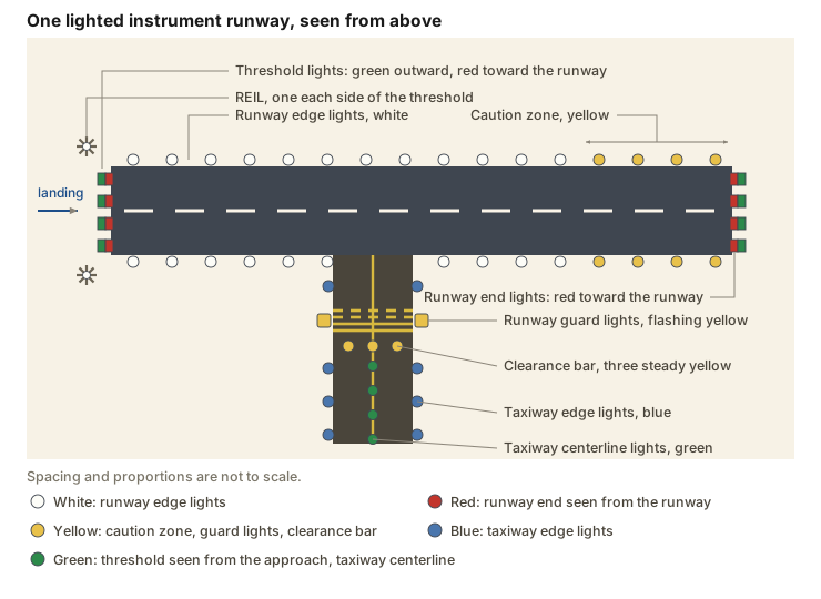
Runway end identifier lights (REIL) are installed at many airfields to provide rapid and positive identification of the approach end of a particular runway. The system consists of a pair of synchronized flashing lights located laterally on each side of the runway threshold, and the lights may be either omnidirectional or unidirectional facing the approach area (AIM 2-1-3).
Runway edge lights outline the edges of runways during periods of darkness or restricted visibility conditions. They are classified according to the intensity they are capable of producing: high intensity runway lights (HIRL), medium intensity runway lights (MIRL), and low intensity runway lights (LIRL). The HIRL and MIRL systems have variable intensity controls, whereas the LIRLs normally have one intensity setting (AIM 2-1-4).
Two color changes interrupt that white outline.
- The runway edge lights are white, except on instrument runways, where yellow replaces white on the last 2,000 feet or half the runway length, whichever is less, to form a caution zone for landings (AIM 2-1-4). PHAK Chapter 14 calls these lights amber.
- The lights marking the ends of the runway emit red light toward the runway to indicate the end of runway to a departing aircraft, and emit green outward from the runway end to indicate the threshold to landing aircraft (AIM 2-1-4).
Precision approach runways add lights inside the pavement. Viewed from the landing threshold, a runway centerline lighting system is white until the last 3,000 feet of the runway. The white lights then alternate with red for 2,000 feet, and the last 1,000 feet are all red (AIM 2-1-5). Touchdown zone lights are two rows of steady-burning white transverse bars either side of the centerline, starting 100 feet beyond the landing threshold (AIM 2-1-5). Land and hold short lights are a row of pulsing white lights across the runway at the hold short point on runways approved for land and hold short operations (LAHSO), and they are on any time LAHSO is in effect (AIM 2-1-5).
Runway status lights are a separate, automatic system. The system is designed to provide a direct indication to you that it is unsafe to enter a runway, cross a runway, or take off from or land on a runway when the system is activated (PHAK Chapter 14). Runway status lights are red. They indicate runway status only and do not indicate clearance to enter a runway or to take off (PHAK Chapter 14). There are two types:
- Runway entrance lights are in-pavement fixtures along the taxiway centerline, from the hold line to the runway edge. When activated, the red lights indicate high speed traffic on the runway, or an aircraft on final approach within the activation area (AIM 2-1-6).
- Takeoff hold lights are in-pavement fixtures in a double row either side of the runway centerline lighting, extending 1,500 feet ahead of the holding aircraft. Illuminated red lights signal that it is unsafe to take off, because the runway is occupied or about to be occupied (AIM 2-1-6).
PHAK Ch 14, "Runway Lighting" and "New Lighting Technologies"; AIM 2-1-3, 2-1-4, 2-1-5, 2-1-6
Taxiway lighting and the lights at the hold line
Taxiway edge lights outline the edges of taxiways during periods of darkness or restricted visibility conditions, and these fixtures emit blue light (AIM 2-1-10). Taxiway centerline lights are steady burning and emit green light. They are located along the taxiway centerline and along designated taxiing paths in portions of runways, ramp, and apron areas (AIM 2-1-10).
Where a taxiway leaves or joins a runway, those centerline lights change color. Taxiway centerline lead-off and lead-on lights are alternate green and yellow, beginning with green, installed from the runway centerline to one centerline light position beyond the runway holding position or the instrument landing system (ILS) critical area holding position (AIM 2-1-5).
Three light systems mark the holding position that the markings lesson introduced as four painted lines.
- Runway guard lights are installed at taxiway and runway intersections to enhance their conspicuity in low visibility conditions, and they may be used in all weather conditions. They are either a pair of elevated flashing yellow lights installed on either side of the taxiway, or a row of in-pavement yellow lights installed across the entire taxiway, at the runway holding position marking (AIM 2-1-10).
- Clearance bar lights are three in-pavement steady-burning yellow lights installed at holding positions on taxiways. They increase the conspicuity of the holding position in low visibility conditions, and they may also be installed to indicate the location of an intersecting taxiway during periods of darkness (AIM 2-1-10).
- Stop bar lights confirm the ATC clearance to enter or cross the active runway in low visibility conditions, below 1,200 feet runway visual range. A stop bar is a row of red unidirectional steady-burning in-pavement lights across the entire taxiway at the runway holding position, with elevated steady-burning red lights on each side (AIM 2-1-10).
AIM 2-1-5, 2-1-10; PHAK Ch 14, "Taxiway Lights"
Pilot-controlled lighting
Airport lighting is controlled by ATC at towered airports. At nontowered airports the lights may be on a timer, and where a flight service station (FSS) is located at an airport, FSS personnel may control the lighting (PHAK Chapter 14).
Radio control of lighting is available at selected airports to provide airborne control of lights by keying the aircraft's microphone (AIM 2-1-8). It is often available at locations without specified hours for lighting, and where there is no control tower or FSS, and at locations with a part-time tower or FSS when that facility is closed (AIM 2-1-8). All lighting systems which are radio controlled at an airport, whether on a single runway or multiple runways, operate on the same radio frequency (AIM 2-1-8).
The control system is a three-step control responsive to 7, 5, or 3 microphone clicks, keyed within 5 seconds (AIM 2-1-8, Table 2-1-3):
| Key mike | Function |
|---|---|
| 7 times within 5 seconds | Highest intensity available |
| 5 times within 5 seconds | Medium or lower intensity (lower REIL or REIL off) |
| 3 times within 5 seconds | Lowest intensity available (lower REIL or REIL off) |
Suggested use is to always initially key the mike 7 times, which assures that all controlled lights are turned on to the maximum available intensity. If desired, adjustment can then be made, where the capability is provided, to a lower intensity by keying 5 or 3 times (AIM 2-1-8). All lighting is illuminated for a period of 15 minutes from the most recent time of activation, and it may not be extinguished prior to the end of that period (AIM 2-1-8).
Because airports using the same frequency lie close together, radio controlled lighting receivers may be set at a low sensitivity requiring the aircraft to be relatively close to activate the system. Even when the lights are already on, key the mike as directed when overflying an airport of intended landing, so that a full 15 minutes of lighting duration is available (AIM 2-1-8).
The Chart Supplement lists the types of lighting, the runway, and the activating frequency for every public use airport with an FAA standard system (AIM 2-1-8). The common traffic advisory frequency (CTAF) activates the lights at many airports, but other frequencies are also used, and the activating frequency is not printed on the sectional chart (AIM 2-1-8).
AIM 2-1-7, 2-1-8 and TBL 2-1-3; PHAK Ch 14, "Control of Airport Lighting"
Obstruction lights
Obstruction lights warn pilots of the presence of obstructions during daytime and nighttime conditions, and they are found both on and off an airport (PHAK Chapter 14). Obstructions may be marked or lighted in any of the following ways (PHAK Chapter 14):
- Red obstruction lights flash or emit a steady red color during nighttime operations, and the obstructions are painted orange and white for daytime operations.
- High intensity white obstruction lights flash high intensity white during the daytime, with the intensity reduced for nighttime.
- Dual lighting combines flashing red beacons and steady red lights for nighttime operation with high intensity white lights for daytime operations.
PHAK Ch 14, "Obstruction Lights"; AIM 2-2-3
Wake turbulence strength and behavior
Wake turbulence is a function of an aircraft producing lift, resulting in the formation of two counter-rotating vortices trailing behind the aircraft (AIM 7-4-1). The drag lesson derived those wingtip vortices from the pressure difference that drives air around each tip.
Wake turbulence can impose rolling moments exceeding the roll-control authority of an encountering aircraft (AIM 7-4-1). The ability to counteract that roll depends primarily on the wingspan and the counter-control responsiveness of the encountering aircraft. It is more difficult for an aircraft whose wingspan is short relative to the generating aircraft, so pilots of short span aircraft must be especially alert to vortex encounters (AIM 7-4-3).
Weight, speed, wingspan, and the shape of the generating aircraft's wing all govern the strength of the vortex (AIM 7-4-3). Vortex strength increases proportionately to an increase in operating weight or a decrease in aircraft speed. Since the turbulence from a dirty aircraft configuration hastens wake decay, the greatest vortex strength occurs when the generating aircraft is heavy, clean, and slow (AIM 7-4-3). The extension of wing flaps tends to reduce the separation between vortices and hastens wake decay (AC 90-23H paragraph 7.3.2). The extension of landing gear tends to hasten the decay of vortices by creating turbulence that interacts with the wake flow field.
Four behaviors let you picture where the wake is (AIM 7-4-4):
- An aircraft generates vortices from the moment it rotates on takeoff to touchdown, because trailing vortices are a by-product of wing lift.
- The vortices remain spaced a bit less than a wingspan apart, drifting with the wind, at altitudes greater than a wingspan from the ground.
- Vortices from larger aircraft sink at a rate of several hundred feet per minute, slowing their descent and diminishing in strength with time and distance behind the generating aircraft. Fly at or above the preceding aircraft's flight path, altering course as necessary to avoid the area directly behind and below it.
- When the vortices of larger aircraft sink close to the ground, within 100 to 200 feet, they tend to move laterally over the ground at a speed of 2 or 3 knots.
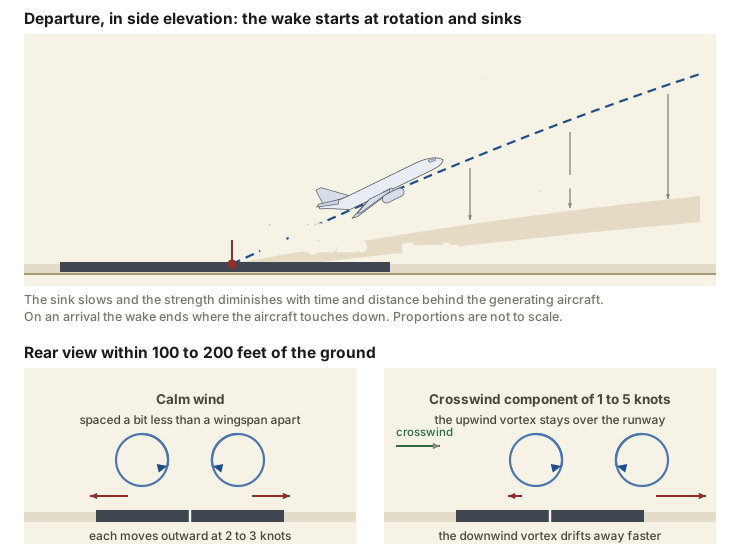
A crosswind decreases the lateral movement of the upwind vortex and increases the movement of the downwind vortex (AIM 7-4-4). A light wind with a cross-runway component of 1 to 5 knots can therefore leave the upwind vortex in the touchdown zone for a period of time and hasten the drift of the downwind vortex toward another runway. A tailwind condition can move the vortices of the preceding aircraft forward into the touchdown zone (AIM 7-4-4).
AIM 7-4-1, 7-4-3, 7-4-4; PHAK Ch 14, "Wake Turbulence," "Vortex Strength," and "Vortex Behavior"; AC 90-23H paragraphs 7.3.2 and 7.4.2.3.1
Avoiding another aircraft's wake
Avoid the area below and behind the wake generating aircraft, especially at low altitude where even a momentary wake encounter could be catastrophic (AIM 7-4-5). Pilots should be particularly alert in calm wind conditions, and where vortices could remain in the touchdown area, drift from a nearby runway, or sink into the traffic pattern from other airport operations (AIM 7-4-5).
The AIM recommends a procedure for each situation (AIM 7-4-6):
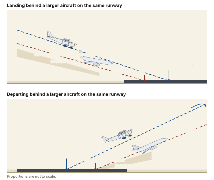
- Landing behind a larger aircraft on the same runway. Stay at or above the larger aircraft's final approach flight path, note its touchdown point, and land beyond it.
- Landing behind a larger aircraft when the parallel runway is closer than 2,500 feet. Consider possible drift to your runway, stay at or above the larger aircraft's final approach flight path, and note its touchdown point.
- Landing behind a larger aircraft on a crossing runway. Cross above the larger aircraft's flight path.
- Landing behind a departing larger aircraft on the same runway. Note the larger aircraft's rotation point and land well prior to it.
- Landing behind a departing larger aircraft on a crossing runway. Note its rotation point. If that point is past the intersection, continue the approach and land prior to the intersection. If the larger aircraft rotates prior to the intersection, avoid flight below its flight path and abandon the approach unless a landing is ensured well before reaching the intersection.
- Departing behind a larger aircraft. Note its rotation point and rotate prior to it, then continue climbing above the larger aircraft's climb path until turning clear of its wake. Avoid subsequent headings which will cross below and behind a larger aircraft.
- Intersection takeoffs on the same runway. Be alert to adjacent larger aircraft operations, particularly upwind of your runway. If an intersection takeoff clearance is received, avoid a subsequent heading which will cross below a larger aircraft's path.
- Departing or landing after a larger aircraft has executed a low approach, missed approach, or touch-and-go landing. Ensure that an interval of at least 2 minutes has elapsed before your takeoff or landing.
- En route. Avoid flight below and behind a large aircraft's path. If a larger aircraft is observed above on the same track, adjust your position laterally, preferably upwind.
Controllers are required to apply no less than minimum required separation to all aircraft operating behind a super or heavy aircraft, and to small aircraft operating behind a Boeing 757, when the aircraft are IFR, or VFR and receiving Class B, Class C, or terminal radar service area (TRSA) airspace services, or VFR and being radar sequenced (AIM 7-4-9). For a departure from the same threshold, two minutes or the appropriate radar separation is provided when takeoff will be behind a heavy aircraft, and controllers may not reduce or waive that interval (AIM 7-4-9). You may request additional separation for wake turbulence avoidance, and that request should be made as soon as practical on ground control and at least before taxiing onto the runway (AIM 7-4-9).
A controller will give a VFR aircraft in communication with the tower, which in the tower's opinion may be adversely affected by wake turbulence from a larger aircraft, the position, altitude, and direction of flight of that aircraft, followed by the phrase "CAUTION - WAKE TURBULENCE" (AIM 7-4-6).
AIM 7-4-5, 7-4-6, 7-4-8, 7-4-9; PHAK Ch 14, "Vortex Avoidance Procedures"
What the rest of this unit adds
This lesson has covered the beacon, the approach light systems, the four kinds of visual glideslope indicator, the runway and taxiway lights and their colors, the runway status lights, pilot-controlled lighting, obstruction lights, and the strength, behavior, and avoidance of wake turbulence.
- Radio Communications covers the position reports made on the CTAF, the words of a self-announce call, and the automatic terminal information service (ATIS) and the automated weather stations.
- Communicating with Air Traffic Control covers towered-airport phraseology, the taxi clearance and its readback, the acceptance or refusal of a LAHSO clearance, the light gun signals for a radio failure, and compliance with ATC instructions under 14 CFR 91.123.
- Reading the Sectional Chart covers the airport symbol, the star that marks a rotating beacon, the airport diagram and its hot spots, and the rest of the chart legend.
The lights on the ground show you the runway and its glidepath, and the aircraft that used the runway before you leaves a wake that you cannot see.
- Key the mike 7 times first at a nontowered field at night, then reduce intensity if you want to. Seven clicks brings every controlled light up at maximum, and the 15 minutes runs from that keying.
- Fly the glidepath the light units define. Below the glidepath a two-bar VASI shows both bars red and a four-unit PAPI shows four red. On a runway served by a visual approach slope indicator, 14 CFR 91.129(e)(3) requires an airplane to stay at or above the glide path until a lower altitude is necessary for a safe landing, and 91.129(e)(4) still permits normal bracketing maneuvers to remain on it.
- Note the rotation point or the touchdown point of the larger aircraft ahead of you before you commit. Those two marks on the pavement are what every wake avoidance procedure references.
- Treat a light quartering tailwind as the condition that keeps a wake where you are about to fly. The upwind vortex stays near the centerline, and the tailwind component forces the pair further down the runway.
Check your understanding
Answer from memory, without scrolling back up. Recalling it yourself is what makes it stick.
A beacon ahead of you flashes white and green at night. The airport below it is?
A beacon flashing white and green is at a lighted land airport. A military beacon also flashes white and green, but it inserts two quick white flashes between the green flashes. (AIM 2-1-9)
A beacon flashing white and yellow is at a lighted water airport. The military beacon is told apart by the dual-peaked white flashes between its green flashes, which this beacon does not show.
You see the beacon running at noon at a Class D airport. That often indicates?
In Class B, Class C, Class D and Class E surface areas, daylight operation of the beacon often indicates that the ground visibility is less than 3 miles and/or the ceiling is less than 1,000 feet. (AIM 2-1-9)
The two figures are 3 statute miles of ground visibility and a 1,000-foot ceiling. There is no regulatory requirement to run the beacon, so check the weather rather than the light.
A two-bar VASI shows the far bar red over the near bar white. You are?
Red over white is the on glidepath indication. Both bars white is above the glidepath and both bars red is below it. (PHAK Ch 14, Figure 14-29)
Each unit shows white above its beam boundary and red below it. Seeing white from the near bar and red from the far bar places you between the two boundaries, which is the glidepath.
On a runway served by a visual approach slope indicator, 14 CFR 91.129(e)(3) requires you to?
The paragraph requires an altitude at or above the glide path until a lower altitude is necessary for a safe landing, and 91.129(e)(4) still permits normal bracketing maneuvers above or below it. (14 CFR 91.129(e)(3) and (e)(4))
The requirement is at or above, not below, and it is not a demand for exact tracking. Paragraph (e)(4) expressly permits normal bracketing maneuvers conducted to remain on the glide path.
A four-unit PAPI shows three white units and one red unit. You are?
Three white and one red is the slightly high indication at about 3.2 degrees. Two white and two red is on the glidepath. (PHAK Ch 14, Figure 14-30)
Reds accumulate from the runway side as you descend. One red means only the highest-angle unit has changed, so you are still slightly above the 3 degree path.
You are landing at night on an instrument runway. The edge lights ahead of you turn yellow, and red lights show at the far end. Those two colors mean?
Yellow replaces white on the last 2,000 feet or half the runway length, whichever is less, to form a caution zone for landings. The lights marking the runway end emit red toward the runway to show the end to a departing aircraft, and green outward to show the threshold to landing aircraft. (AIM 2-1-4)
Taxiway edge lights are blue and a stop bar lies across a taxiway rather than a runway. Yellow runway edge lights mark the caution zone, and the red lights facing back down the pavement mark the runway end.
Approaching a nontowered field at night, you key the mike 7 times in 5 seconds. The result is?
Keying 7 times assures that all controlled lights are turned on to the maximum available intensity, and all lighting is illuminated for 15 minutes from the most recent activation. (AIM 2-1-8)
Seven clicks is the maximum-intensity step and it brings up every controlled system, not the edge lights alone. Five and three clicks step the intensity down from there.
The greatest wake vortex strength occurs when the generating aircraft is?
Vortex strength increases with operating weight and with a decrease in speed, and turbulence from a dirty configuration hastens wake decay, so the worst case is heavy, clean, and slow. (AIM 7-4-3)
Extended flaps and gear hasten decay rather than concentrating the wake, and strength rises as speed falls. Heavy, clean, and slow is the combination to watch.
Which wind condition keeps a wake in the touchdown zone and along final the longest?
The crosswind component resists the outward movement of the upwind vortex, and the tailwind component forces the vortices forward, so the light quartering tailwind requires maximum caution. (AIM 7-4-4; AC 90-23H para 7.4.2.3.1)
The wake vortex decay rate increases with wind speed, so a strong wind is not the hazardous case. The light quartering tailwind is, because the upwind vortex stays near the centerline and the vortices move forward.
You are landing behind a larger aircraft on the same runway. You should?
For landing behind a larger aircraft on the same runway, the recommended procedure is to stay at or above the larger aircraft's final approach flight path, note its touchdown point, and land beyond it. (AIM 7-4-6)
The vortices sink below and behind the generating aircraft, and its wake ends where it touches down. Staying above its path and landing beyond that point keeps you clear of both.
Go deeper (primary source): read AIM Chapter 2, Section 1, Airport Lighting Aids and AIM Chapter 7, Section 4, Wake Turbulence in full, then read AC 90-23H, Aircraft Wake Vortex Encounter Risk Mitigation, which gives the drift and decay figures behind the AIM's procedures.