Private Pilot · Unit 3 · 30 min
Fuel, Electrical, and Other Systems
By the end of this lesson you will know:
- how fuel reaches the engine by gravity in a high-wing trainer and by pumps in a low-wing airplane
- how to identify the correct fuel grade by color and why fuel is sampled from the sumps before every flight
- why the mixture is leaned in cruise, what running too rich or too lean costs, and how the EGT gauge guides the setting
- how the battery, alternator, and bus bar share the electrical load, and what the ammeter tells you
- why the master switch has separate BAT and ALT halves
- where cabin heat comes from and why a defective exhaust risks carbon monoxide
The systems around the engine
The previous lesson, The Engine and Propeller, followed the energy of combustion from the fuel entering the cylinders out to the propeller. This lesson covers the systems that surround that engine: the fuel system that delivers clean fuel to it, the electrical system that supplies the airplane's lights, radios, and instruments, and the small systems built onto the same hardware, including cabin heat, pitot heat, and the stall warning. None of these produces thrust, but each one keeps the engine fed or the cockpit working, and a failure in any of them changes how you fly the airplane.
The fuel system: tanks to engine
The fuel system has one job: deliver clean fuel to the engine without interruption, at every power setting and in every normal attitude. How it does that depends on where the tanks sit relative to the engine, and that is the first place a high-wing trainer and a low-wing airplane differ.
In a high-wing trainer such as the Cessna 172, the fuel tanks sit in the wings, above the engine. Fuel flows down to the engine under its own weight through a gravity-feed system, with no pump required. Because both tanks sit above the engine and drain downhill together, the airplane can draw from both at once, which is why the fuel selector has a BOTH position alongside LEFT and RIGHT. This is the quiet advantage the cockpit lesson mentioned when it introduced the selector.
A low-wing airplane cannot feed by gravity. Its tanks sit below the engine, so the fuel has to be lifted. An engine-driven pump does that work in flight, and an electric boost pump is plumbed in the line as well: it supplies fuel pressure for starting, before the engine-driven pump is turning fast enough, and it serves as a backup if the engine-driven pump fails. A low-wing selector typically reads LEFT or RIGHT with no BOTH position, because a pump drawing from two tanks at once could pull air from whichever tank empties first.
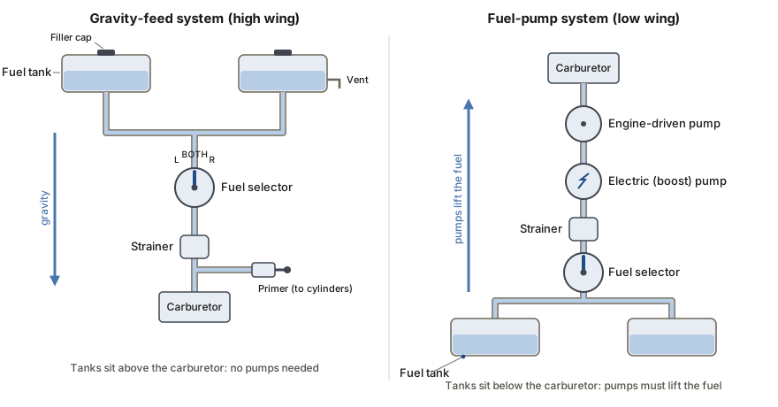
Between the tank and the engine, both systems share the same parts. Each tank is vented, either through the filler cap or a separate vent line, so that outside air replaces the fuel as it drains; a blocked vent lets the tank pressure fall below the outside air and can slow or stop the fuel flow. A fuel strainer at the low point of the system traps water and sediment before the fuel reaches the engine. The fuel primer draws fuel from the line and sprays it directly into the cylinders' intake ports to help start a cold engine; it locks in place when it is not in use, because an unlocked primer can draw fuel into the intake in flight and make the mixture too rich.
Federal rules require a fuel quantity gauge to read accurately at only one point: empty, when the usable fuel reaches zero. Between full and empty the gauge is allowed to be approximate. So the accurate measure of how much fuel you have is the preflight visual check, where you look into each tank and read the level against a calibrated tab or a dipstick. In flight the gauge shows a trend, not a number to plan a flight around.
PHAK Ch 7, "Fuel Systems"
Fuel grades and contamination
The engine is built for a specific fuel. Using a grade lower than the engine requires invites the explosive combustion the previous lesson described as detonation, which spikes cylinder pressure and can destroy the engine. To make the grade easy to confirm, aviation gasoline is dyed a distinct color for each grade, and jet fuel is left nearly colorless so it stands out from all of them.
| Grade | Dye color | Typical use |
|---|---|---|
| 100LL | Blue | Most current piston trainers |
| 80 | Red | Older low-compression engines |
| 100 | Green | Higher-compression piston engines |
| Jet A | Colorless to straw | Turbine engines, not piston |
The color is a safety check you make with your eyes. A piston trainer runs on 100LL, which is dyed blue. Jet fuel is colorless to straw-colored and smells of kerosene rather than gasoline, so if the fuel drawn from the tank is clear and smells of kerosene, the airplane has been fueled with the wrong product and must not be flown until it is corrected. Misfueling a piston engine with jet fuel is a known cause of engine failure shortly after takeoff.
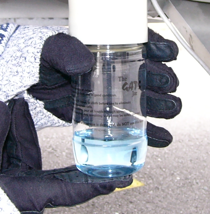
The main contaminant to look for is water. Water is denser than fuel, so it settles to the lowest points of the tanks and lines. Those low points have drains, called sumps, at each tank and at the strainer. Before every flight you drain a sample from each sump into a transparent container and inspect it: the fuel should be the right color, clear rather than cloudy, and free of water droplets and sediment. Water shows up as beads or a separate layer at the bottom of the sample. You keep draining until the sample comes out clean. To limit the water in the first place, top the tanks off after the last flight of the day, because full tanks leave little air space for the moisture in humid air to condense out overnight.
One more step protects against fire during refueling. Fuel flowing through a hose and nozzle builds up a static electric charge, and a spark from that charge near fuel vapor could ignite it. To prevent this, the airplane is grounded, connected to the fuel source with a ground wire before fueling begins, so both are at the same electrical potential and no spark can jump between them.
PHAK Ch 7, "Fuel Grades" and "Fuel Contamination"
Leaning and the mixture in cruise
The mixture control is the one fuel-system control you adjust continuously in flight: it sets how much fuel the carburetor meters into the incoming air. The previous lesson explained that the carburetor keeps metering fuel for dense sea-level air, so as air thins with altitude the mixture grows too rich until you lean it back to the correct ratio. This lesson takes that from the reason the control exists to how you use it in cruise, and to the gauge that guides the setting.
Running too rich has a cost even after the engine is started. Excess fuel lowers the cylinder temperature and does not burn completely; the unburned fuel deposits carbon that fouls the spark plugs, the engine runs rough and loses power, and the fuel that never burns is pumped overboard as waste. That waste matters because the tanks are finite and, as the fuel section explained, the gauges are trusted only at empty. Your endurance depends on a known, predictable fuel burn, and an over-rich mixture makes the burn higher than planned.
Leaning corrects this, but it can be overdone in the other direction. If you lean in cruise and then descend without enriching the mixture again, the air grows denser as you lose altitude while the fuel stays reduced, and the mixture becomes too lean. An over-lean mixture at high power raises the cylinder temperature and can bring on the same detonation the previous lesson warned about, reached this time through too little fuel rather than the wrong grade, along with rough operation, overheating, and lost power. This is why the mixture is enriched before a descent and before any high-power operation near the ground.
The reference for setting the mixture is the exhaust gas temperature (EGT) gauge. It measures the temperature of the exhaust gas leaving the cylinders at the exhaust manifold, and that temperature depends on the fuel-air ratio: as you lean from a rich setting, combustion becomes more complete and the EGT rises to a peak; leaning past the peak, each charge carries less fuel, so less heat is released and the excess air absorbs part of it, and the EGT falls again. Because the temperature moves with the ratio, the gauge lets you set the mixture against a measured value rather than by feel, and leaning to the value your handbook specifies reduces fuel consumption for a given power. The specific offsets from peak EGT and the choice between a best-power and a best-economy setting belong to the performance unit, Unit 9; here the point is that the EGT gauge is the instrument that makes leaning precise.
PHAK Ch 7, "Mixture Control" and "Exhaust Systems"
The electrical system
Two sources of electrical power work together. The battery is a chemical store of energy: it turns the starter to crank the engine, supplies power before the engine is running, and serves as a reserve if the other source fails. The alternator is turned by the engine and produces the airplane's electrical power once the engine is running, both supplying the loads and recharging the battery.
Light airplanes use either a 14-volt or a 28-volt electrical system, paired with a 12-volt or a 24-volt battery. The alternator's output is held a little above the battery's voltage by the voltage regulator, and that difference is what drives charging current back into the battery. The regulator holds the system voltage steady as engine speed and electrical load change. Power from the alternator and the battery meets at the bus bar, a common conductor that distributes it to every circuit in the airplane. Each circuit is protected by a fuse or, more often, a resettable circuit breaker that opens when the current exceeds a safe value, isolating a fault before it can overheat the wiring. A breaker that has opened may be reset once; a breaker that opens again indicates a persistent fault; leave it open and have the circuit inspected.
The lights, radios, fuel gauges, flap motor, pitot heat, stall warning, and starter all run on electricity. The ignition deliberately does not: as the engine lesson established, the magnetos generate their own spark from the engine's rotation. Because of that, a complete electrical failure stops the radios and the electric instruments but does not stop the engine.
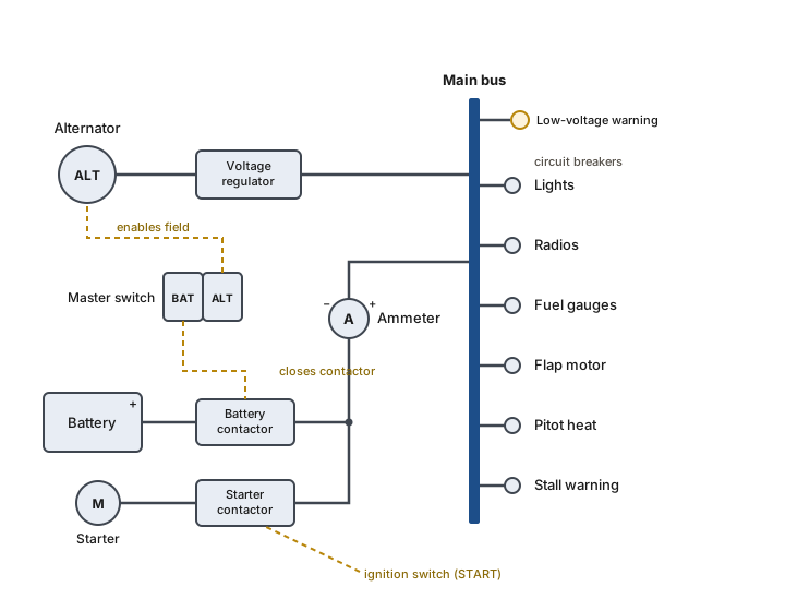
The cockpit lesson introduced the master switch as a split rocker with BAT and ALT halves that you flip together in normal use, but it did not say why the switch is split. The two halves control the battery and the alternator separately so that a failing alternator can be switched off on its own. With ALT off the airplane runs on the battery alone, and you shed electrical load, turning off lights, unneeded radios, and pitot heat, to make the battery's limited charge last long enough to land. In the schematic, the BAT half closes the battery contactor that connects the battery to the bus, and the ALT half enables the alternator's field so it can produce power.
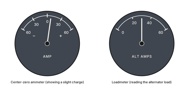
The ammeter tells you whether the battery is charging or discharging. It reads zero at the center. A needle on the plus side means the alternator is producing more current than the loads require and the surplus is charging the battery, which is normal after starting. A needle on the minus side means the loads exceed what the alternator supplies and the battery is making up the difference. A full-scale minus reading points to alternator failure, with the battery carrying the entire load; a full-scale plus reading points to a regulator malfunction overcharging the battery. Some airplanes fit a loadmeter instead, which reads from zero upward and shows the total current the alternator is supplying: a higher reading means more electrical load, and a drop to zero means the alternator has stopped producing. A low-voltage warning light on the panel comes on when the bus voltage falls below the alternator's normal output, usually the first sign that the alternator has stopped charging.
Starting the engine draws far more current than any other load, so it has its own heavy path. Turning the ignition key to START energizes the starter contactor, a heavy-duty relay that connects the battery directly to the starter motor. Once the engine is running you release the key, the contactor opens, and the starter drops out of the circuit while the alternator takes over supplying the airplane.
PHAK Ch 7, "Electrical System"
Cabin heat and the other small systems
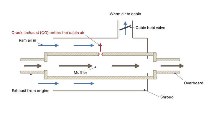
Cabin heat burns no fuel of its own. Outside ram air is routed through a shroud, a thin metal jacket around the engine's exhaust muffler, where the hot exhaust passing inside warms it. A cabin heat valve in the duct controls how much of that warmed air reaches the cabin. Because the air is heated by flowing around the outside of the exhaust, this arrangement carries a specific hazard: a crack in the muffler or the exhaust pipe can let exhaust gas, which contains carbon monoxide, leak into the air on its way to the cabin.
Two more small systems run off the electrical bus you just met. Pitot heat is an electric heating element inside a small pressure probe, the pitot tube, that feeds the airspeed indicator. The element keeps the probe's opening free of ice so the airspeed reading stays valid in visible moisture near freezing. The probe and the instruments it drives are the subject of the next lesson, The Pitot-Static Instruments. The stall warning is a small vane or tab on the wing's leading edge wired to a horn or light in the cabin. As the angle of attack increases toward the wing's critical angle, the airflow shifts on the leading edge and lifts the vane, closing an electric circuit that sounds the horn. It is set to trip just below the critical angle of attack; in level flight that margin gives you the warning a few knots above the stall speed, as Stalls and Spins described. Recall that the stall is defined by that angle, not by a fixed airspeed.
One engine-driven accessory serves the instruments rather than the engine: a vacuum pump turned by the engine drives a stream of air that spins the gyroscopes inside some of the flight instruments. How those instruments use those spinning gyroscopes is the subject of The Gyroscopic Instruments and Compass, later in this unit.
PHAK Ch 7, "Exhaust Systems" and "Electrical System"; PHAK Ch 8
Check your understanding
Answer from memory, without scrolling back up. Recalling it yourself is what makes it stick.
Why does a low-wing airplane need fuel pumps that a high-wing trainer does not?
With the tanks below the engine, gravity cannot feed the fuel up, so an engine-driven pump and an electric boost pump lift it. A high-wing trainer feeds downhill. (PHAK Ch 7)
The reason is height: the low-wing tanks sit below the engine, so pumps must lift the fuel. A high-wing trainer's tanks feed down by gravity.
When is a fuel quantity gauge required to read accurately?
The rule requires accuracy only at empty, so the preflight visual check of each tank is the real measurement of how much fuel you have. (PHAK Ch 7)
Accuracy is required only at empty. Everywhere else the gauge may be approximate, so you measure the fuel by looking into the tanks before flight.
Aviation gasoline graded 100LL is dyed which color?
100LL is dyed blue. Jet fuel is left nearly colorless and smells of kerosene, so a clear kerosene-smelling sample means the airplane was misfueled. (PHAK Ch 7)
100LL is blue. Jet fuel is colorless to straw and smells of kerosene, which is how you catch a piston airplane fueled with the wrong product.
Why are the fuel sumps drained into a clear container before flight?
Water is denser than fuel and settles to the sumps, so a clear sample shows any water beads or sediment. You drain until the sample comes out clean. (PHAK Ch 7)
The sump drain checks for contamination: water and debris settle to the low points, and a clear container reveals them. It does not vent or warm the fuel.
Why is the airplane grounded to the fuel source before refueling?
Moving fuel builds a static charge, and a spark near the vapor could ignite it. Grounding puts the airplane and the fuel source at the same potential. (PHAK Ch 7)
The hazard is static electricity from the flowing fuel. Grounding the airplane to the source prevents a spark that could ignite the vapor.
Descending into denser air without enriching the mixture leaves it?
Denser air with the fuel still reduced makes the mixture lean; an over-lean mixture at high power raises cylinder temperature and can bring on detonation. (PHAK Ch 7)
Descending adds air while the fuel stays low, so the mixture goes lean. Over-lean at high power overheats the cylinders and can cause detonation.
The exhaust gas temperature gauge is the leaning reference because?
Because EGT changes with the fuel-air ratio, it lets you set the mixture against a measured temperature rather than by feel. (PHAK Ch 7)
The gauge works because exhaust gas temperature tracks the fuel-air ratio. Air pressure and blade angle are not what it measures for leaning.
After an alternator failure, switching ALT off leaves the airplane on?
With the alternator offline the battery is the only source, so you turn off nonessential loads to stretch its limited charge to a landing. (PHAK Ch 7)
The battery is now the only source, and its charge is limited, so the correct move is to shed load, not add it or ignore it.
On a center-zero ammeter, a needle on the plus side shows?
A plus reading means the alternator supplies more than the loads need and the surplus charges the battery, which is normal after starting. (PHAK Ch 7)
Plus is charging. A minus reading is discharging, and a full-scale minus points to alternator failure with the battery carrying the load.
Why can a cracked exhaust muffler put carbon monoxide in the cabin?
Cabin heat is ram air warmed by flowing around the muffler, so a crack lets exhaust gas, and its carbon monoxide, leak into that air path. (PHAK Ch 7)
The warmed air passes around the outside of the exhaust, so a crack contaminates it with exhaust gas. The heat is not routed exhaust or oil vapor.
Go deeper (primary source): read the "Fuel Systems," "Fuel Contamination," "Electrical System," and "Exhaust Systems" sections of PHAK Chapter 7. The pitot tube and airspeed indicator continue in the next lesson, The Pitot-Static Instruments, and the vacuum-driven gyros in The Gyroscopic Instruments and Compass.