Private Pilot · Unit 3 · 30 min
The Pitot-Static Instruments
By the end of this lesson you will know:
- which instruments run on static pressure alone and which one also needs the pitot tube
- how the altimeter turns static pressure into an altitude and how to read its three hands
- the five kinds of altitude and why cold air or falling pressure leaves you lower than the altimeter shows
- how the vertical speed indicator reads a rate of climb and why it lags a few seconds
- what the airspeed indicator measures and why true airspeed outruns indicated airspeed as you climb
- what the colored arcs and V-speeds mean, and how each instrument fails when a port is blocked
Three of the instruments in front of you run on nothing but air pressure. They carry no gyroscope and draw no electricity to work. The altimeter tells you how high you are, the vertical speed indicator tells you how fast that height is changing, and the airspeed indicator tells you how fast the wing is moving through the air. All three read from the same two pressure sources, and this lesson explains what each one actually measures, how to read it, and how it fails.
Two pressures, one system
The whole system works from two pressures. The first is static pressure, the ordinary barometric pressure of the air around the airplane. It is present whether the airplane is moving or parked, and it falls as the airplane climbs because there is less air overhead. The second is the pressure the airplane's own motion adds. As the airplane moves forward, air is pressed into a forward-facing probe, and the pressure inside that probe rises above the static value by an amount that depends on how fast the airplane is going. This added pressure is the dynamic pressure, also called ram or impact pressure.
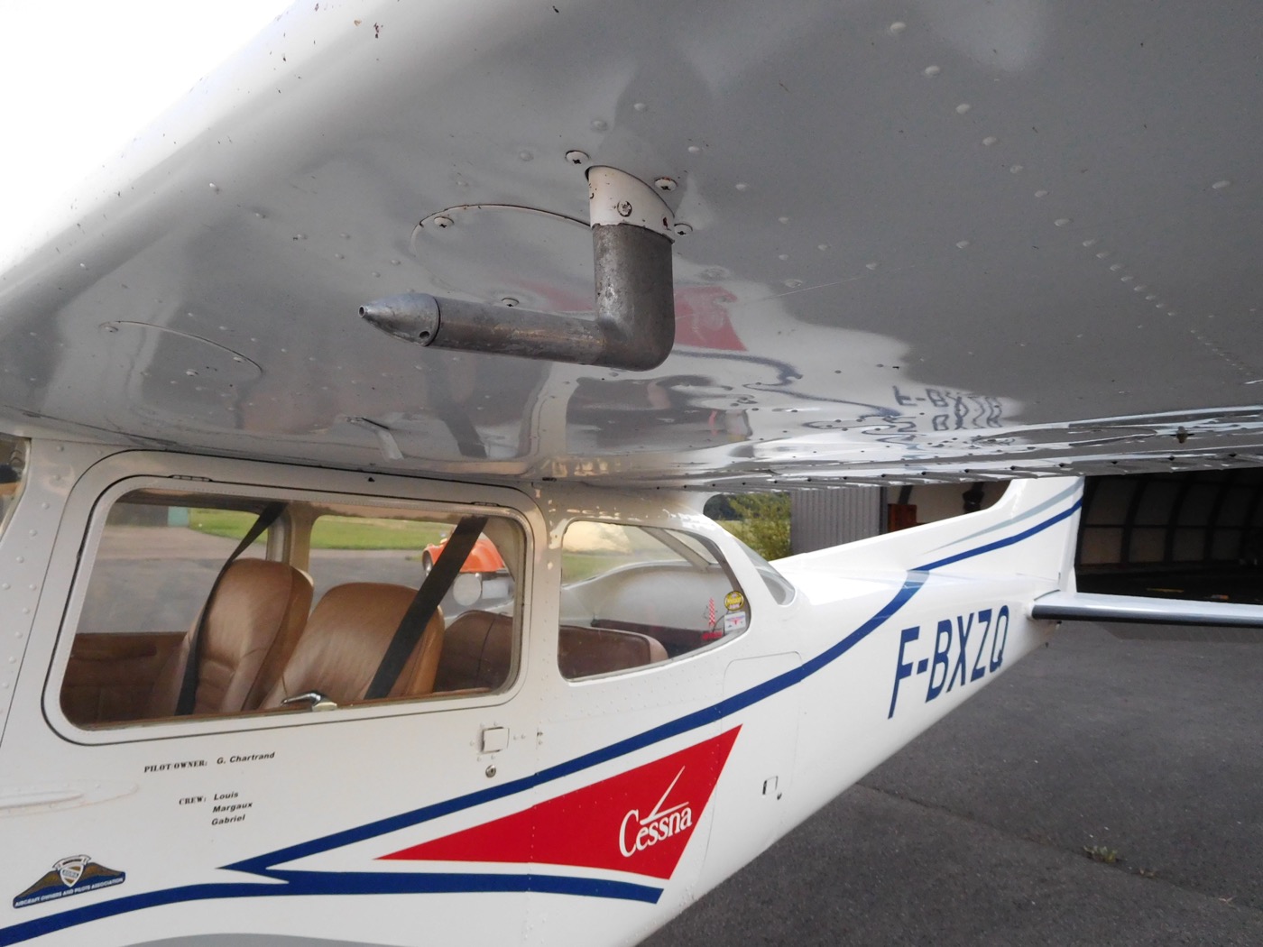
Two openings collect these pressures. The pitot tube is the forward-facing probe under the wing in the photo above; its front opening senses the total of static plus dynamic pressure, and a small drain hole at the back lets moisture escape. The static port is a flush opening on the side of the fuselage, set where the passing air is undisturbed, so it senses static pressure alone. The previous lesson introduced the pitot heat that keeps ice out of that probe in visible moisture near freezing; the probe itself and the instruments it drives are the subject here.
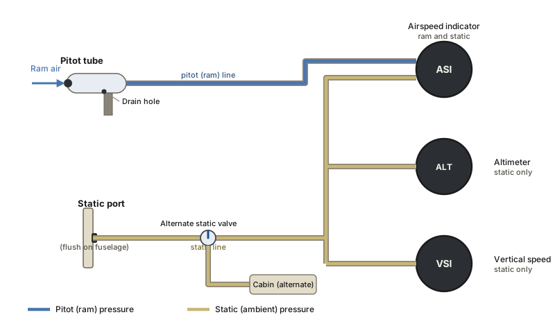
Keep track of which instrument uses which source; the blockage section at the end of this lesson follows directly from it. The altimeter and the vertical speed indicator connect to the static line only. The airspeed indicator connects to both: it receives the pitot pressure on one side and the static pressure on the other, so that the static pressure cancels and only the dynamic pressure is left to move the needle. This division predicts how each instrument fails.
Airplanes with glass cockpits read the same two probes. An air data computer measures the pitot and static pressures electronically and computes altitude, vertical speed, and airspeed for the display, but the pressures it works from are identical to the ones these mechanical instruments use. The pitot tube and static port on a glass-cockpit airplane are the same hardware you see here.
PHAK Ch 8, "Pitot-Static Flight Instruments"
The altimeter
The altimeter measures static pressure and displays it as a height. Inside the sealed case is a stack of aneroid wafers: thin sealed metal capsules with an internal reference pressure of 29.92 inches of mercury. Static pressure from the port fills the case around the wafers. When the airplane climbs, the surrounding static pressure falls, the wafers expand, and a mechanical linkage turns that expansion into a higher reading. When the airplane descends, the higher static pressure compresses the wafers and the reading falls. The instrument is an aneroid barometer with its face marked in feet rather than in inches of mercury.
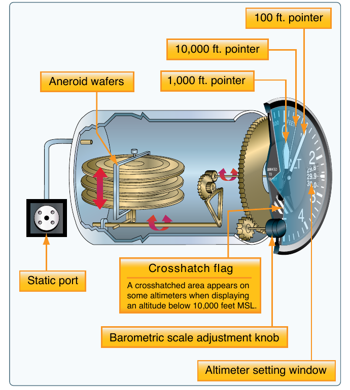
Because the altimeter measures pressure, its reading is only as accurate as the reference pressure you give it. That reference is the altimeter setting, the local pressure corrected to sea level, which you dial into the small window on the face, the Kollsman window. Setting the current local value makes the instrument read height above mean sea level. As pressure varies from place to place, you reset the window along the route so the indicated altitude stays close to your true altitude; the regulations that require this appear in Unit 4, in the Operating Rules for Every Flight lesson.
The three-pointer face is read like a clock with three hands of different weight. The long needle on top reads hundreds of feet, one full turn per thousand. The short, wide needle reads thousands. The long, thin needle with the inverted triangle at its tip reads tens of thousands. An indication with the hundreds pointer at 5 and the thousands pointer between 2 and 3 is two thousand five hundred feet. Misreading the thousands pointer by a full digit is a known error, which is why the numbers are cross-checked against the flight and the terrain rather than read once and trusted.
PHAK Ch 8, "Altimeter" and "Principle of Operation"
The five altitudes and the nonstandard atmosphere
The word altitude means something different depending on what it is measured against, and five kinds matter to you. The atmosphere is the reason they diverge. The standard atmosphere is a reference model in which sea-level pressure is 29.92 inches of mercury, sea-level temperature is 15 degrees Celsius, and both fall at fixed rates with height. The real atmosphere rarely matches it, and every departure from the standard model separates one kind of altitude from another.
- Indicated altitude is what you read off the altimeter with the current setting in the window.
- True altitude is the actual height above mean sea level. Airport, terrain, and obstacle elevations on charts are true altitudes.
- Absolute altitude is the height above the terrain directly below the airplane, above ground level.
- Pressure altitude is what the altimeter shows when 29.92 is set in the window: the height above the standard-pressure level. You read it by setting 29.92 and noting the indication.
- Density altitude is pressure altitude corrected for nonstandard temperature: the altitude at which the air has the density the airplane is actually feeling. The airplane performs as though it were at that altitude, and its effect on takeoff, climb, and landing is the subject of Unit 9, Performance and Weight and Balance. Here it is enough to hold the definition.
The gap between indicated and true altitude is where the nonstandard atmosphere becomes a hazard. Setting the current local altimeter setting corrects for the pressure at the reporting station, but it does not correct for temperature, and it goes stale as you fly away from that station. Two situations leave the airplane lower than the altimeter shows. The first is flying from an area of high pressure toward an area of low pressure without resetting the window: the altimeter keeps reading the old, higher pressure as though it were still present, so it overstates your height, and your true altitude is lower than indicated. The second is flying into air colder than standard: cold air is denser, so the pressure levels the altimeter is reading are packed closer to the ground than the standard model assumes, and again your true altitude is lower than indicated.
Both cases share one memory aid: from a high to a low, or from hot to cold, look out below. Both leave the airplane closer to the terrain than the instrument indicates, which is why a colder-than-standard day over mountains calls for a higher indicated altitude to keep the same real clearance, and why you reset the altimeter to each new station along the route.
PHAK Ch 8, "Effect of Nonstandard Pressure and Temperature" and "Types of Altitude"
The vertical speed indicator
The vertical speed indicator (VSI) shows the rate at which the airplane is climbing or descending, in feet per minute. It runs on static pressure alone, but it works by comparing that pressure against a delayed copy of itself. Inside the case is a diaphragm connected directly to the static line. The space around the diaphragm, inside the sealed case, is also connected to the static line, but through a narrow restriction called the calibrated leak.
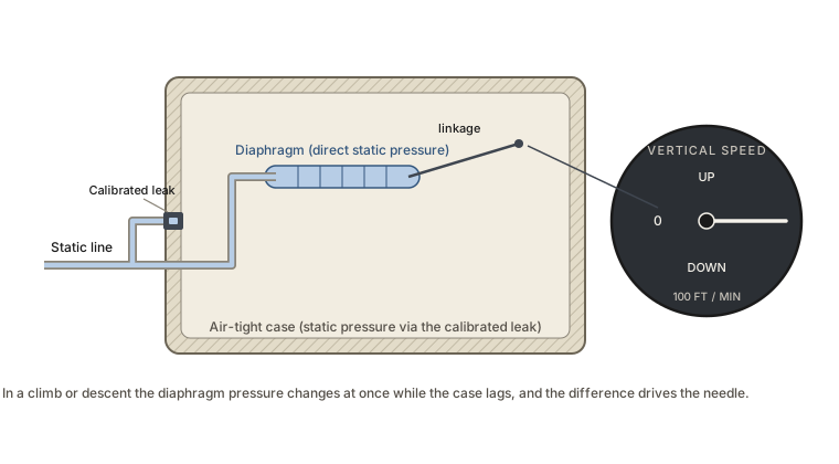
In level flight the diaphragm pressure and the case pressure are equal and the needle rests at zero. When the airplane begins to climb, the static pressure falls, and the pressure inside the diaphragm follows immediately while the case pressure lags behind through the leak. The difference between the two pushes the needle to show a climb; in a descent the difference reverses and the needle shows a descent. Because the case pressure needs a moment to catch up through the leak, the instrument has a built-in lag: the needle moves at once to show the direction of change, but the steady value it settles on, the actual rate, is only trustworthy after roughly six to nine seconds of stable flight. The first movement is a trend; the settled reading is a rate.
PHAK Ch 8, "Vertical Speed Indicator"
The airspeed indicator
The airspeed indicator (ASI) is a differential pressure gauge. It admits the total pressure from the pitot tube to one side of a diaphragm and the static pressure from the port to the other side. The static pressure common to both cancels, and what remains to deflect the diaphragm is the dynamic pressure, the pressure the airplane's motion adds. Dynamic pressure is exactly the quantity the wing responds to when it makes lift, so the airspeed indicator reads, in effect, how hard the air is pressing on the airframe.
This is why the airspeed a wing stalls at is quoted as an indicated airspeed. Stalls and Spins established that the wing stalls at a fixed angle of attack, not at a fixed speed, and that the stall speed is simply the speed at which steady flight demands that angle. Because both the wing and the airspeed indicator respond to the same dynamic pressure, the indicated airspeed at the stall stays nearly constant regardless of altitude, even though the airplane is moving faster through the air up high. The four airspeeds you need to keep straight are these:
- Indicated airspeed (IAS) is the number read straight off the dial, uncorrected.
- Calibrated airspeed (CAS) is indicated airspeed corrected for the small installation and instrument errors, largest at low speed and high angle of attack.
- True airspeed (TAS) is the airplane's actual speed through the air mass.
- Groundspeed is true airspeed corrected for wind: the speed over the ground, less with a headwind and more with a tailwind.
True airspeed pulls ahead of indicated airspeed as you climb. The engine lesson noted that the air thins with altitude; thinner air produces less dynamic pressure at a given true speed, so to build the same dynamic pressure the airplane must move faster through the thinner air. The airspeed indicator reads dynamic pressure, so for a given calibrated airspeed (in a trainer, nearly the same as indicated) true airspeed grows by roughly two percent per thousand feet. At altitude the wing feels the indicated airspeed while the airplane covers ground at the higher true airspeed, which is the number you use for flight planning.
PHAK Ch 8, "Airspeed Indicator"
Airspeed markings and V-speeds
The colored arcs on the dial turn several structural and aerodynamic limits into marks you can read at a glance. Each boundary is a certificated speed, a V-speed, and the arcs place them where the needle passes.
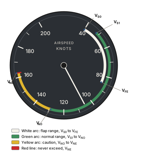
- The white arc is the flap operating range. Its lower end is VS0, the stall speed in the landing configuration with gear and flaps down, and its upper end is VFE, the maximum speed with flaps extended.
- The green arc is the normal operating range. Its lower end is VS1, the stall speed in a clean configuration, and its upper end is VNO, the maximum structural cruising speed, not to be exceeded except in smooth air.
- The yellow arc above the green is a caution range, to be flown only in smooth air and only with care.
- The red line is never-exceed speed (VNE), beyond which flutter or structural failure can occur.
One important speed is deliberately absent from the dial. Maneuvering speed (VA), which Load Factor and Turns introduced as the speed below which a full control deflection stalls the wing before it can overload the structure, is not marked because it changes with weight: it is lower when the airplane is light and higher when it is heavy. A fixed mark on the dial would be wrong at every weight but one, so maneuvering speed is given on a placard and in the airplane's Pilot's Operating Handbook (POH) instead. You look it up for the day's weight.
PHAK Ch 8, "Airspeed Indicator Markings" and "Other Airspeed Limitations"
Blockages
Because the readings come from pressures in tubes, a blocked tube produces a steady, wrong indication rather than an obviously failed instrument. Blockages come from ice, dirt, or insects, which is why the pitot tube and static ports are checked on every preflight and why the pitot cover is removed before flight. The way an instrument fails depends on which opening blocks, and it follows directly from the plumbing in the first figure.
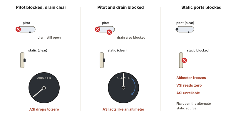
Pitot tube blocked, drain hole clear. Ram air can no longer enter, and the pressure already trapped in the line escapes through the open drain until it falls to the ambient static value. With the same static pressure now on both sides of the diaphragm, the airspeed indicator senses no dynamic pressure and the reading falls to zero. The altimeter and vertical speed indicator, which do not use the pitot tube, are unaffected.
Pitot tube and drain both blocked. Now the pressure in the pitot line is sealed in and cannot change. The static side, still open, keeps responding to altitude. So the airspeed indicator responds only to changes in static pressure: climb and the static pressure falls while the trapped pitot pressure holds, so the needle reads higher; descend and it reads lower. The instrument behaves like an altimeter, moving with altitude and ignoring actual airspeed.
Static ports blocked, pitot clear. This is the worst case because it disables all three static instruments. The altimeter freezes at the altitude where the blockage occurred, because the trapped static pressure can no longer change. The vertical speed indicator reads a constant zero, since the diaphragm and case pressures can never differ. The airspeed indicator keeps moving but reads wrong: it indicates low above the blockage altitude and high below it. The defense is the alternate static source, a valve that admits static pressure from inside the cabin. Cabin pressure is slightly lower than the outside static pressure, so on the alternate source the altimeter reads a little high and the airspeed a little fast. The errors are repeatable properties of the airframe, so the manufacturer measures them and publishes the corrections in the POH. In an airplane without an alternate source, breaking the glass face of the vertical speed indicator vents the static system to the cabin as a last resort, at the cost of that instrument.
Two defenses cover these failures. The pitot heat introduced in the previous lesson keeps ice out of the probe, and the alternate static source restores the static instruments when the ports block. Both are checklist items with procedures in the POH. Knowing which instruments each one restores lets you diagnose a bad reading in flight.
PHAK Ch 8, "Blockage of the Pitot-Static System"
Check your understanding
Answer from memory, without scrolling back up. Recalling it yourself is what makes it stick.
Which instruments use static pressure only, and which needs both sources?
The altimeter and VSI read static pressure alone. The ASI compares the pitot's total pressure against static, leaving dynamic pressure. (PHAK Ch 8)
The airspeed indicator is the one that needs both the pitot and the static sources. The altimeter and VSI use static pressure only.
Standard sea-level conditions in the reference atmosphere are?
The standard atmosphere fixes sea-level pressure at 29.92 inches of mercury and temperature at 15 degrees Celsius. (PHAK Ch 8)
The reference values are 29.92 inches of mercury and 15 degrees Celsius at sea level, with both falling at fixed rates aloft.
How do you read pressure altitude off the altimeter?
Pressure altitude is what the altimeter shows with 29.92 set in the window: the height above the standard-pressure level. (PHAK Ch 8)
Dial 29.92 into the Kollsman window and read the indication. That is pressure altitude, the height above the standard-pressure level.
Flying from high pressure to low without resetting the altimeter means?
The altimeter still reads the old higher pressure, so it overstates your height: from a high to a low, look out below. (PHAK Ch 8)
Without a reset the altimeter overstates height, so true altitude is lower than indicated. The same is true flying into colder air.
When you begin a climb, the vertical speed indicator shows?
The needle moves at once to show the direction, but the case pressure lags through the calibrated leak, so the true rate settles after roughly six to nine seconds. (PHAK Ch 8)
Trend comes first, rate second. The calibrated leak delays the case pressure, so the settled rate is trustworthy only after several seconds.
The white and green arcs on the airspeed indicator run?
The white arc is the flap range from the landing-configuration stall to the flaps-extended limit; the green arc is the normal range from the clean stall to the structural cruise limit. (PHAK Ch 8)
White is the flap range, Vs0 to Vfe. Green is the normal range, Vs1 to Vno. The lower ends are the two stall speeds.
Why is maneuvering speed missing from the airspeed dial?
Maneuvering speed is lower when light and higher when heavy, so a fixed mark would be wrong at every weight but one; it lives on a placard instead. (PHAK Ch 8)
It varies with weight, lower when light and higher when heavy, so it cannot take a single mark. You look it up for the day's weight.
If the pitot tube and its drain both block, the airspeed indicator?
With the pitot pressure sealed in, only the open static side responds, so the needle rises in a climb and falls in a descent, tracking altitude. (PHAK Ch 8)
Both blocked traps the pitot pressure while static still works, so the ASI tracks altitude like an altimeter. It zeroes only if the drain stays clear.
A blocked static system with a clear pitot means?
Trapped static pressure freezes the altimeter and holds the VSI at zero; opening the alternate static source restores them, with small corrections listed in the POH. (PHAK Ch 8)
The altimeter freezes and the VSI reads zero. The fix is the alternate static source, which reads slightly high on altitude and airspeed.
As you climb, true airspeed compared with indicated airspeed?
Thinner air makes less dynamic pressure at a given true speed, so for a fixed calibrated airspeed the true speed rises, about two percent per thousand feet. (PHAK Ch 8)
True airspeed pulls ahead of indicated as density falls. The wing feels the indicated value while the airplane covers ground at the higher true speed.
Go deeper (primary source): read the "Pitot-Static Flight Instruments," "Altimeter," "Vertical Speed Indicator," "Airspeed Indicator," and "Blockage of the Pitot-Static System" sections of PHAK Chapter 8. The gyroscopic instruments and the magnetic compass, which close this unit, come next in The Gyroscopic Instruments and Compass.