Private Pilot · Unit 3 · 30 min
The Gyroscopic Instruments and Compass
By the end of this lesson you will know:
- which three instruments contain a spinning gyroscope and which one needs no power at all
- how rigidity in space and precession each drive a gyroscopic instrument
- why the attitude and heading indicators run on the vacuum system while the turn coordinator runs on electricity
- what the attitude indicator, heading indicator, and turn coordinator each display, and how to read the inclinometer ball
- how variation, deviation, and magnetic dip make the compass read in error, including the turning and acceleration errors
- how a vacuum failure shows itself and which instruments keep working through it
The previous lesson accounted for three of the six round instruments in front of you, the ones that run on air pressure alone. Three remain. Each of those three contains a small wheel spinning at high speed, a gyroscope, and each uses one of two properties of a spinning gyroscope to measure something the pressure instruments cannot: the airplane's attitude, its heading, and its rate of turn. A seventh instrument, the magnetic compass on the windshield post, also senses direction and needs no power source at all. This lesson explains what each instrument senses, how it is driven, and how each one fails.
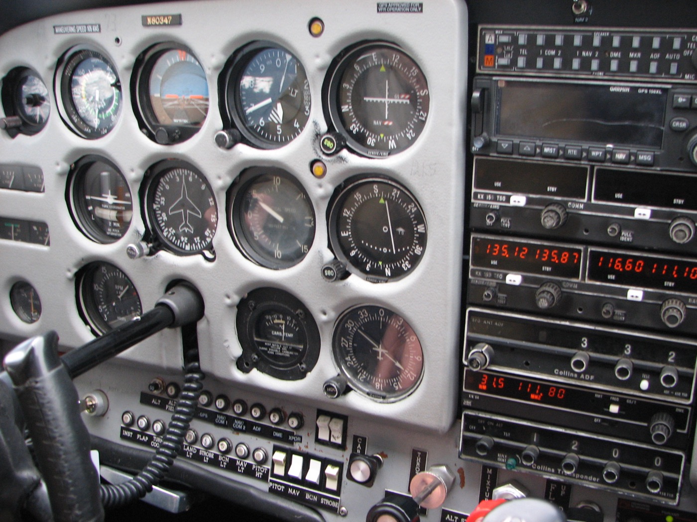
What a spinning gyroscope gives you
A gyroscope is a wheel built heavy for its size and spun at high speed on low-friction bearings. Once it is spinning, it has two properties that no stationary object has, and each gyroscopic instrument is built around one of them.
The first is rigidity in space: a spinning gyroscope holds the plane of its rotation fixed in space, and its axis keeps pointing in a constant direction, no matter how the frame around it is tilted or turned. Mount the wheel in a set of gimbal rings so it is free to rotate in any direction, and the wheel stays put while the airplane and the instrument case move around it. That fixed reference is what the attitude indicator and the heading indicator both exploit: each holds a steady reference that the airplane is measured against.
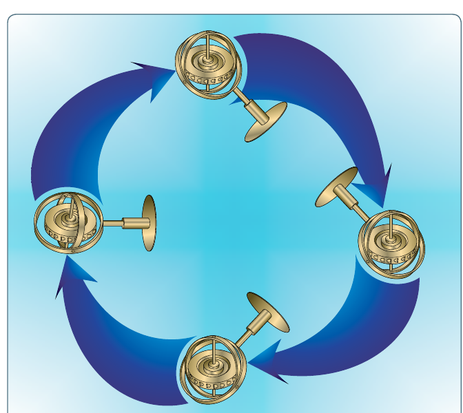
The second property is precession. The lesson on left-turning tendencies introduced the 90-degree rule as it acts on the spinning propeller: a force applied to the rim of a spinning disc does not take effect where it is applied but at a point 90 degrees farther around the rim, in the direction of rotation. Gyroscopic precession is that response, and the turn instruments put it to work. When the airplane yaws, it applies a force to the gyro's rim; precession carries that force a quarter-turn around and tilts the gyro, and the amount of tilt measures how fast the airplane is turning.
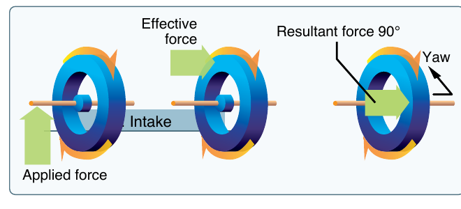
Each instrument uses one property. Rigidity in space gives the attitude and heading indicators their fixed reference; precession gives the turn coordinator its measured tilt.
PHAK Ch 8, "Gyroscopic Flight Instruments" and "Gyroscopic Principles"
Who powers what
A gyroscope has to be kept spinning, and light airplanes use two independent power sources to do it. Most of the panel's gyros are spun by air. The vacuum system is an engine-driven pump, a filter, a relief valve, and the plumbing that connects them. The lesson on the airplane's electrical and other systems noted that one engine-driven accessory serves the instruments rather than the engine; this is it. The pump draws a stream of air through the cases of the attitude and heading indicators, and that airstream strikes vanes on each gyro rotor and spins it, the way moving water turns a waterwheel. The suction it develops is usually between 4.5 and 5.5 inches of mercury, and a suction gauge on the panel reads whether the system is producing it.
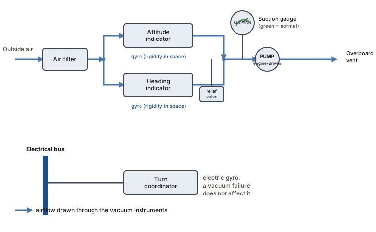
The third gyro instrument, the turn coordinator, is driven by an electric motor from the airplane's electrical bus instead. That division is deliberate. Because the vacuum system and the electrical system are independent, one failure cannot take away every gyro at once: if the vacuum pump quits, the electrically driven turn coordinator keeps working and still shows whether the wings are level, and if the electrical system fails, the vacuum-driven attitude and heading indicators keep spinning. At least one source of bank information survives either failure.
PHAK Ch 8, "Sources of Power"
The attitude indicator
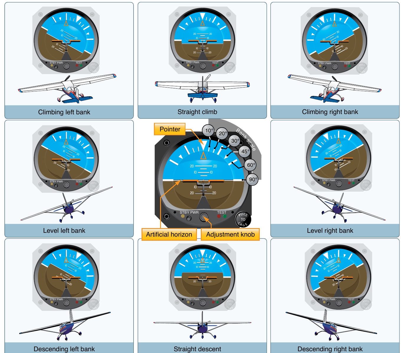
The attitude indicator is the only instrument that shows the airplane's pitch and bank directly. Its gyro spins in a horizontal plane and relies on rigidity in space, so it holds that plane fixed while the airplane moves. A horizon bar is fixed to the gyro and stays level with the real horizon; a small fixed airplane symbol is attached to the case and moves with the airplane. You read attitude from the relationship between the two, exactly as you read the real airplane against the real horizon: nose above the bar is a climb, a wing dropped below it is a bank. Strictly, the airplane rotates around the steady gyro rather than the gyro moving.
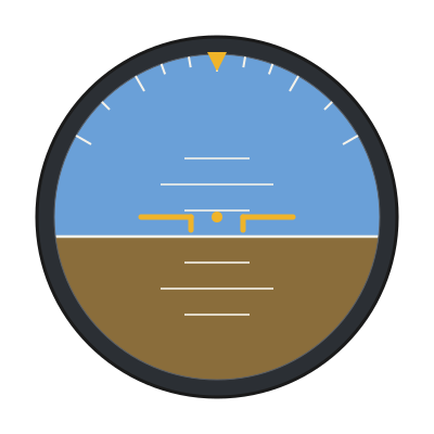
The dial is built to be read the way the world looks: blue sky above the horizon bar, brown ground below it, with a scale across the top marking bank angle. The grid below shows how nine common attitudes appear on the face, each a combination of a pitch and a bank. Because it presents pitch and bank together and immediately, the attitude indicator is the instrument a pilot leans on most when the natural horizon is lost in cloud, which is why keeping it running matters and why its failure is treated seriously later in this lesson.
PHAK Ch 8, "Attitude Indicator"
The heading indicator
The heading indicator displays the airplane's heading on a 360-degree card, and it too works by rigidity in space. Its rotor spins in a vertical plane with a compass card fixed to it; the rotor holds its position in space, so as the airplane turns, the case revolves around the steady card and the heading under the top index changes. The card is marked with the cardinal letters N, E, S, and W and a number every 30 degrees with the final zero dropped, so 3 reads 030 degrees, 12 reads 120 degrees, and 21 reads 210 degrees. Because a steady gyro drives it rather than a magnet, the heading indicator is smooth and steady to read, without the swinging and the errors the magnetic compass shows in turns and speed changes.
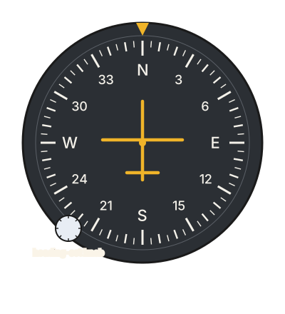
The heading indicator has one important limitation: it contains no magnet, so it has no way to sense north. It only holds whatever heading you set into it. Two effects make that setting drift. Friction in the bearings precesses the gyro slowly off its position, and because the gyro is fixed in space while the earth rotates beneath it at 15 degrees per hour, the card creeps even in perfect bearings. The two together can amount to several degrees over a quarter of an hour. So you set the heading indicator from the magnetic compass and check it against the compass about every 15 minutes, resetting it when it has drifted. Make the reset in straight, level, unaccelerated flight, because that is the only time the magnetic compass you are copying from is itself reading correctly, for reasons the compass section makes clear.
PHAK Ch 8, "Heading Indicator"
The turn coordinator and the ball
The turn coordinator works by precession rather than rigidity. Its gyro is mounted on a gimbal that is canted, tilted up from level, so that a yaw as well as a roll applies a force to the gyro's rim. Precession carries that force a quarter-turn around and tilts the gyro, and the tilt drives a miniature airplane symbol on the face. As you roll into a turn the symbol banks in the direction of the roll, and once the bank is established the instrument reads the rate of turn, how fast the airplane's heading is changing. Index marks on the face show when you have reached a standard-rate turn, which the lesson on load factor and turns defined as a turn of 3 degrees per second, the rate that carries the airplane all the way around a 360-degree circle in two minutes. The turn coordinator shows the rate and direction of the turn; it does not show the angle of bank.
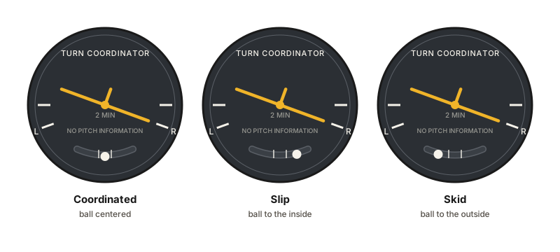
Below the miniature airplane is the inclinometer, a ball in a curved fluid-filled tube. It shows whether the turn is coordinated, meaning the airplane's nose is following the curve of the turn rather than sliding across it. In a coordinated turn the ball rests in the center. A slip is a turn with too little rudder for the bank: the rate of turn is too slow for the angle of bank, the airplane slides toward the inside of the turn, and the ball falls to the inside. A skid is the opposite, too much rudder for the bank: the rate of turn is too great for the bank, the airplane slides toward the outside, and the ball rolls to the outside. In both cases the correction is the same. Remember it as step on the ball: press the rudder pedal on the side the ball has moved to and it returns to center. If the ball is out to the right, you need right rudder.
PHAK Ch 8, "Turn Indicators," "Turn Coordinator," and "Inclinometer"
The magnetic compass
The magnetic compass is the oldest instrument in the airplane and the only self-contained direction source in it: it needs no electrical, vacuum, or pitot-static power, so it keeps working when everything else has failed. Two small bar magnets are attached to a float sealed inside a bowl of clear fluid similar to kerosene. The magnets align with the earth's magnetic field, and a graduated card wrapped around the float carries the headings. You read the heading where the card meets the lubber line, the fixed vertical reference mark on the glass. The float rides on a jewel bearing and its buoyancy takes most of the weight off the pivot, and the fluid damps its swinging.
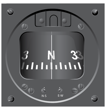
Because the card is fixed to the magnets and you view it from behind, its numbers run in what looks like the reverse of a chart: when you fly north, east lies to your right in the airplane but appears to the left of north on the card. The float and card are also free to tilt only to about 18 degrees of bank; past that the reading becomes erratic. The compass is what you set the heading indicator from, so its readings matter even though you rarely steer by it directly. Its usefulness is limited by a set of errors, which the next section takes in turn.
PHAK Ch 8, "Compass Systems" and "Magnetic Compass"
Why the compass reads in error
The magnetic compass is simple, but it is subject to three sources of error you have to account for. The first two are steady offsets; the third produces errors that appear only while the airplane is turning or changing speed.
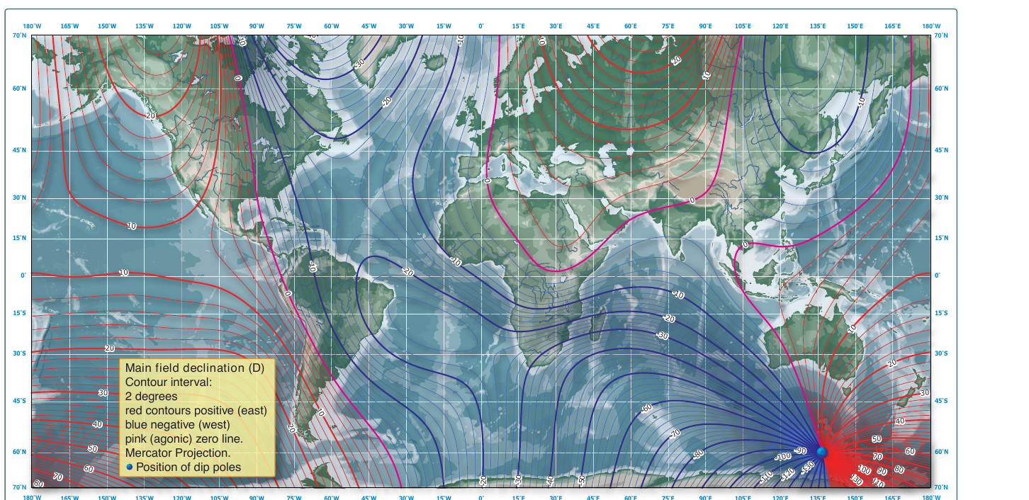
Magnetic variation is the angle between true north, the direction of the geographic pole that charts are drawn to, and magnetic north, the direction the compass points. The two poles are about 1,300 miles apart, so at most places on earth they lie in slightly different directions, and the difference is the variation. Charts show it with isogonic lines, lines joining places of equal variation. Where variation is zero, so that magnetic north and true north lie in the same direction, the line is called the agonic line. Variation depends only on where you are, not on which way you are pointed, so it is the same on every heading at a given place. Converting between true and magnetic direction to plan a course is the work of the navigation unit, in the lesson on pilotage and dead reckoning; here you need only know that variation is the true-versus-magnetic offset built into the earth's geometry.
Compass deviation is error from magnetic fields inside the airplane itself: current flowing in wires, magnetized steel parts, and the airplane's own accumulated magnetism. Unlike variation, deviation depends on the airplane's heading and not on where it is flying, and it changes as electrical equipment is switched on. A mechanic minimizes it by adjusting small compensating magnets in the compass, a task called swinging the compass, and records whatever error is left on a compass correction card mounted near the instrument. Variation comes from the earth's field, deviation from the airframe's; that distinction is the one the knowledge test asks about.
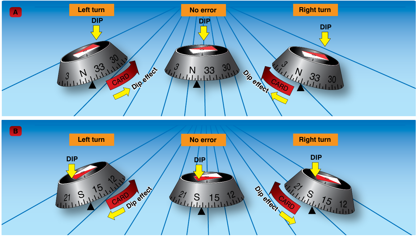
The third error is a consequence of the shape of the earth's field. Magnetic dip is the tilt of the field lines downward toward the earth as you move away from the magnetic equator toward the poles: the field does not run flat along the surface but angles into the ground. The compass is weighted below its pivot to keep the card roughly level so that dip does not tip it in normal flight. But when the airplane banks or changes speed, the card tilts, the downward pull of the field acts on it, and the reading swings. This is the cause of the two error patterns the knowledge test names.
Turning errors appear when you turn through north or south. As you roll into a turn from a northerly heading, the compass is sluggish and lags behind the airplane, and it can briefly indicate a turn in the opposite direction before it catches up. Turning from a southerly heading, it does the reverse and leads, running ahead of the airplane. The rollout rule that follows is remembered as UNOS, undershoot north and overshoot south: roll out of a turn onto a northerly heading a little early because the compass lags, and onto a southerly heading a little late because it leads. The error is largest near the magnetic poles and negligible near the magnetic equator.
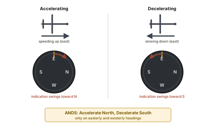
Acceleration errors appear on easterly and westerly headings when the airplane speeds up or slows down. The compass is mounted like a pendulum, so a change in speed tips the card, dip acts on it, and the heading appears to swing even though the airplane has not turned. On an east or west heading, accelerating makes the compass indicate a turn toward north, and decelerating makes it indicate a turn toward south. The memory aid is ANDS, accelerate north and decelerate south. There is no acceleration error on a north or south heading.
PHAK Ch 8, "Variation," "Deviation," "Dip Errors," "Northerly Turning Errors," and "Acceleration Error"
When the gyros fail
A vacuum failure is dangerous because nothing on the failing instruments themselves signals it. If the vacuum pump fails, the attitude and heading indicators do not go dark or freeze. Their gyros spin down over the minutes that follow, lose rigidity as they slow, and drift off their references gradually. The attitude indicator can show a slow, believable lean and the heading indicator a slow wander, and a pilot who reads them without cross-checking can follow them into a bank without noticing. The defenses are the suction gauge, which shows the vacuum has dropped below its normal range, and, in many trainers, a warning light or annunciator that flags low suction. When either appears, treat the attitude and heading indicators as unreliable.
What survives a vacuum failure is what makes the split power sources worth having. The turn coordinator runs on the electrical bus, so it keeps showing whether the wings are level and whether the airplane is turning. The magnetic compass needs no power at all, so it keeps showing heading, with its usual errors. Between the electric turn coordinator and the self-contained compass, you retain both bank and heading information after the vacuum pump quits, which is enough to keep the airplane upright and pointed while you deal with the failure.
PHAK Ch 8, "Sources of Power" and "Heading Indicator"
A note on glass panels
Newer airplanes replace the spinning gyros with an attitude and heading reference system, or AHRS, a set of solid-state sensors that measure the airplane's attitude and rate of turn electronically and a magnetometer that senses magnetic north, all feeding a flat-panel display. An AHRS has no free-spinning wheel to slow down or tumble, so it behaves differently in a failure. The mechanical instruments in this lesson are still the standard of the training fleet, and everything the AHRS presents, attitude, heading, and rate of turn, is the same information described here, shown on a screen instead of a dial.
PHAK Ch 8, "Attitude and Heading Reference System (AHRS)"
Check your understanding
Answer from memory, without scrolling back up. Recalling it yourself is what makes it stick.
Which gyroscopic property makes the attitude and heading indicators work?
A spinning gyro holds its plane fixed in space, giving each instrument a steady reference the airplane is measured against. (PHAK Ch 8)
Both use rigidity in space, the steady fixed reference. Precession is what the turn coordinator uses; dip is a compass error.
How are the three gyro instruments powered, and why that way?
The attitude and heading indicators run on vacuum, the turn coordinator on electricity, so one power failure still leaves bank information. (PHAK Ch 8)
The sources are split on purpose: vacuum drives two, electricity the turn coordinator, so no single failure stops all three gyros.
What does the attitude indicator alone display directly?
Its horizon bar, fixed to a rigid gyro, shows pitch and bank directly, read like the real airplane against the real horizon. (PHAK Ch 8)
Heading belongs to the heading indicator and rate of turn to the turn coordinator. The attitude indicator alone shows pitch and bank.
Why is the heading indicator reset from the compass about every 15 minutes?
The heading indicator only holds a set value; friction and the earth's rotation precess it off, so it is realigned to the compass periodically. (PHAK Ch 8)
It has no magnet of its own, and precession slowly drifts the card, so you reset it from the compass. Leading and lagging are compass errors.
A standard-rate turn on the turn coordinator is?
A standard-rate turn is 3 degrees per second, which goes all the way around in two minutes, read at the coordinator's index marks. (PHAK Ch 8)
Standard rate is 3 degrees per second, two minutes around. The coordinator shows rate, not a specific angle of bank.
In a turn the inclinometer ball is out to the right. You should?
Step on the ball: press the rudder on the side the ball moved to. A ball to the right calls for right rudder. (PHAK Ch 8)
The rule is step on the ball, meaning the rudder on the ball's side. Ball right means right rudder, not left rudder or aileron.
Which error comes from the earth's field, and which from the airplane?
Variation is the true-versus-magnetic offset built into the earth's geometry; deviation is the airframe's own magnetic fields. (PHAK Ch 8)
Variation is the earth's true-versus-magnetic angle; deviation is the airplane's own magnetism, corrected on the compass card.
Rolling into a turn from a northerly heading, the compass?
Near north the dip force makes the card sluggish: it lags and may briefly indicate the opposite direction. Undershoot north on rollout. (PHAK Ch 8)
From a northerly heading the compass lags, so you undershoot north. Leading happens from a southerly heading.
Accelerating on an easterly heading, the compass indicates?
On an east or west heading, accelerate north and decelerate south: the tilted card and dip make it read a turn it is not making. (PHAK Ch 8)
ANDS: accelerating shows a turn toward north, decelerating toward south, on east or west headings only, not toward south here.
The vacuum pump fails in cruise. What happens next?
The vacuum gyros wind down and wander slowly; the electric turn coordinator and the powerless compass keep working. (PHAK Ch 8)
The vacuum instruments drift gradually rather than freezing, and the electric coordinator and self-contained compass are unaffected.
Go deeper (primary source): read the "Gyroscopic Flight Instruments," "Turn Indicators," "Attitude Indicator," "Heading Indicator," and "Compass Systems" sections of PHAK Chapter 8. Applying variation and deviation to a course is taken up in the navigation unit, and why a pilot follows a failing attitude indicator is taken up in the aeromedical unit. This lesson closes Unit 3; the course continues with the regulations of Unit 4, starting with Certificates, Privileges, and Medicals.