Private Pilot · Unit 3 · 25 min
The Engine and Propeller
By the end of this lesson you will know:
- how a reciprocating engine turns piston motion into crankshaft rotation
- the four strokes of the engine cycle and which one delivers power
- how the propeller produces thrust as a rotating airfoil
- how the carburetor meters fuel and why it can ice up in warm air
- why the mixture knob is needed and why the engine carries two magnetos
- how oil and cooling air carry off the heat combustion leaves behind
Opening the cowling
The powerplant is the engine and propeller together, and its job is to convert the chemical energy in fuel into thrust: the forward force that opposes drag and drives the airplane through the air. In The Four Forces of Flight thrust was one of the four forces without an account of where it comes from. This lesson gives that account. It follows the energy from the fuel tank, through combustion in the cylinders, out to the propeller blades that push air rearward, and it explains the induction and ignition systems that make combustion happen and the oil and cooling systems that carry off that heat before it damages the engine.
The fuel, electrical, and cabin-heat systems are the subject of the next lesson, Fuel, Electrical, and Other Systems; this lesson picks up the fuel where it enters the engine and treats the electrical system only where the master switch was left in an earlier lesson.
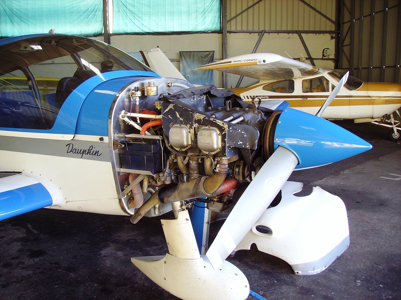
PHAK Ch 7, "Powerplant"
The reciprocating engine
A trainer's engine is a reciprocating engine: it converts the back-and-forth motion of pistons in their cylinders into rotation of a crankshaft. A typical Cessna 172 engine is four-cylinder, horizontally opposed, and air-cooled. Horizontally opposed means the cylinders lie flat in two banks facing each other across the crankshaft, two on each side, which keeps the engine low and narrow behind the propeller and helps cooling air reach every cylinder.
Inside each cylinder, burning fuel and air raise the pressure and drive the piston outward. A connecting rod links the piston to the crankshaft, and as the piston moves the rod turns the crankshaft, the same way your leg turns a bicycle crank. The crankshaft carries that rotation forward to the propeller. Everything else in the engine exists to keep this conversion running: fuel and air arrive through the induction system, the ignition system lights the charge at the right instant, and oil and cooling air carry away the heat that combustion leaves behind.
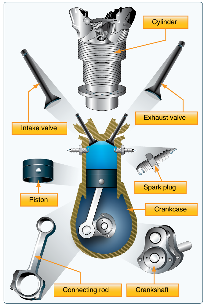
PHAK Ch 7, "Reciprocating Engines"
The four-stroke cycle
Each cylinder repeats a four-stroke cycle, four movements of the piston in a fixed order:
- Intake: the piston moves down, the intake valve opens, and the cylinder draws in a charge of fuel and air.
- Compression: both valves close and the piston moves up, squeezing the charge into a small volume so it burns quickly and releases more of its energy.
- Power: the spark plugs fire near the top of compression, the charge burns, and the rising pressure drives the piston down. This is the only stroke that delivers power to the crankshaft.
- Exhaust: the exhaust valve opens and the rising piston pushes the burned gases out, clearing the cylinder for the next intake.
The piston makes four strokes but the crankshaft turns only twice, so each cylinder delivers one power stroke every two crankshaft revolutions. A single cylinder would drive the crankshaft in pulses. The four cylinders fire at staggered points in the cycle, so while one is on its power stroke another is drawing in its charge and another is compressing, and the crankshaft receives a nearly continuous push. The heavy crankshaft and propeller carry the engine through the gaps by their own inertia.
PHAK Ch 7, "Reciprocating Engines"
The propeller is a rotating wing
The propeller does for the airplane what the wing does for lift, turned on its side. Each blade is an airfoil, and as it spins it meets the air at an angle of attack and produces an aerodynamic force. On a wing that force is lift, acting upward; on a propeller blade that force tilts forward, and its forward component is thrust. The wing lesson, How a Wing Generates Lift, established that an airfoil's force depends on the angle at which it meets the relative wind and on how fast that air moves past it. Both of those facts shape the propeller.
A propeller blade meets air from two directions at once: the air the airplane flies into from the front, and the air the blade sweeps into as it rotates. The rotational speed of a point on the blade is its distance from the hub times the rate of rotation, so a point near the tip travels much faster through the air than a point near the hub, even though both turn at the same RPM. If the blade were flat, the fast-moving tip and the slow-moving root would meet their combined airflow at very different angles, and much of the blade would be at a useless or even negative angle of attack.
The fix is built into the blade: its blade angle, the angle between the blade's chord line and its plane of rotation, is largest near the hub and decreases steadily toward the tip. This twist holds each station of the blade near the same effective angle of attack despite the rising speed toward the tip, so the whole blade produces thrust efficiently rather than just one band of it.
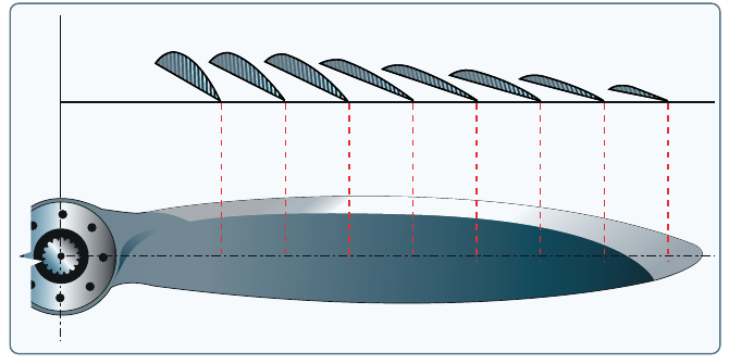
The propeller also sets up the airplane's left-turning tendencies, which is why a trainer needs right rudder on the takeoff roll and in the climb. Those tendencies get their own treatment in the lesson Left-Turning Tendencies; here it is enough to know the spinning propeller is the source.
PHAK Ch 7, "Propeller"
Fixed pitch, constant speed, and reading power
A fixed-pitch propeller has its blade angle set once, at manufacture. That single angle is a compromise: a blade angle that climbs well is too coarse for efficient cruise, and one tuned for cruise climbs poorly, so the designer picks a middle setting. Almost every primary trainer uses a fixed-pitch propeller. On this installation the engine's power is read from the tachometer, which shows crankshaft speed in revolutions per minute; with the blade angle fixed, RPM tracks how hard the engine is working, and the throttle is the only power control.
A constant-speed propeller instead changes its blade angle in flight. A governor senses engine speed and adjusts the blade angle to hold a selected RPM, keeping the engine at an efficient speed while conditions change, much as a car's transmission holds engine speed as the load varies. On these installations RPM alone no longer tells you the power, so a second gauge is added: the manifold pressure gauge shows the pressure of the fuel-air charge in the intake manifold, and power is set from the combination of manifold pressure and RPM. Constant-speed propellers belong to higher-performance and complex airplanes; you should recognize the term and the gauge, but you will train and test on a fixed-pitch trainer.
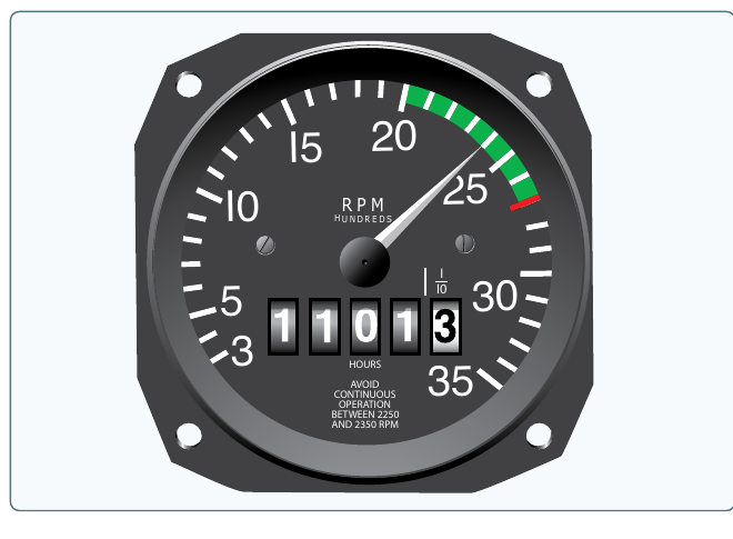
PHAK Ch 7, "Propeller"
The carburetor
Before the charge can burn, fuel and air must be mixed in the right proportion. On most trainers a float-type carburetor does this. Its metering trick is the same one that lets a wing make lift. Intake air on its way to the cylinders is drawn through a venturi, a narrowing in the passage. As the wing lesson established in How a Wing Generates Lift, Bernoulli's principle says that where a fluid speeds up, its pressure falls; the air accelerates through the narrow throat, and its pressure there drops below the pressure in the fuel around it.
A fuel line opens into the throat of the venturi. The pressure drop there draws fuel out of the line and into the airstream, where it atomizes and vaporizes, and the fuel-air mixture flows on to the cylinders. The more air the engine draws, the faster it moves through the venturi, the lower the throat pressure falls, and the more fuel it pulls, so fuel delivery follows airflow. The throttle you met in the cockpit lesson works a butterfly valve downstream of the venturi: opening it lets more mixture reach the cylinders, and the engine speeds up.
PHAK Ch 7, "Induction Systems"
Carburetor ice
The same venturi that meters the fuel also chills the carburetor, and this is where carburetor ice comes from. Two effects cool the throat at once: the air's pressure drop in the venturi lowers its temperature, and the fuel absorbs heat as it evaporates into the airstream, the same way sweat cools your skin. Together they can drop the temperature inside the carburetor 60 to 70 degrees Fahrenheit below the outside air. If the air holds enough moisture, that moisture freezes onto the throat and the throttle valve.
The trap is that this happens in weather that feels far too warm for ice. Carburetor ice is most likely when the outside air is below about 70 degrees Fahrenheit and the humidity is above 80 percent, and it is possible at outside temperatures as high as 100 degrees in very humid air. The ice narrows the passage and chokes off the mixture. On a fixed-pitch airplane the first sign is a gradual, unexplained drop in RPM at a fixed throttle setting, and if it goes unchecked the engine runs rough and can quit.
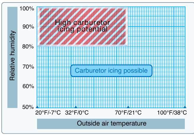
The cure is carburetor heat, the control you met in the cockpit lesson. Pulling it routes intake air past a shroud around the hot exhaust before it reaches the carburetor, and that warm air melts the ice. Applying carburetor heat to an engine that already has ice produces a telling sequence: RPM drops a little further at first, because the warm air is less dense and the melting ice passes through the engine as water and roughens the running, and then, as the ice clears, the RPM rises and smooths out above where it had sagged. That momentary drop followed by recovery is the confirmation that ice was present.
PHAK Ch 7, "Carburetor Icing" and "Carburetor Heat"
Fuel injection
Newer trainers replace the carburetor with fuel injection, which meters fuel and sprays it directly at each cylinder's intake port instead of into a single shared venturi. Because there is no venturi to chill and no pool of fuel evaporating in the induction air, the fuel-injected engine has no carburetor ice and no carburetor heat knob to pull. Delivering a measured amount of fuel to each cylinder also evens the mixture across the four cylinders, which a single carburetor cannot do as precisely. The tradeoffs are a more involved starting procedure, especially when the engine is hot, and greater sensitivity to fuel contamination. That is why some 172s on the ramp have a carburetor heat control and others do not.
PHAK Ch 7, "Fuel Injection"
Why the mixture knob exists
Air thins as you climb: a cubic foot of air at 8,000 feet holds far fewer oxygen molecules than the same volume at sea level. The carburetor, though, meters fuel by the airflow through its venturi, and it goes on delivering roughly the amount of fuel that matched sea-level air. With less air but the same fuel, the mixture grows too rich, which wastes fuel, fouls the spark plugs, and costs power. The mixture control from the cockpit lesson is the pilot's remedy: leaning it reduces the fuel to match the thinner air and restores the correct fuel-to-air ratio. The specific leaning procedure and its effect on performance numbers belong to the performance unit later in the course; here the point is only why the control has to exist.
PHAK Ch 7, "Mixture Control"
Two magnetos
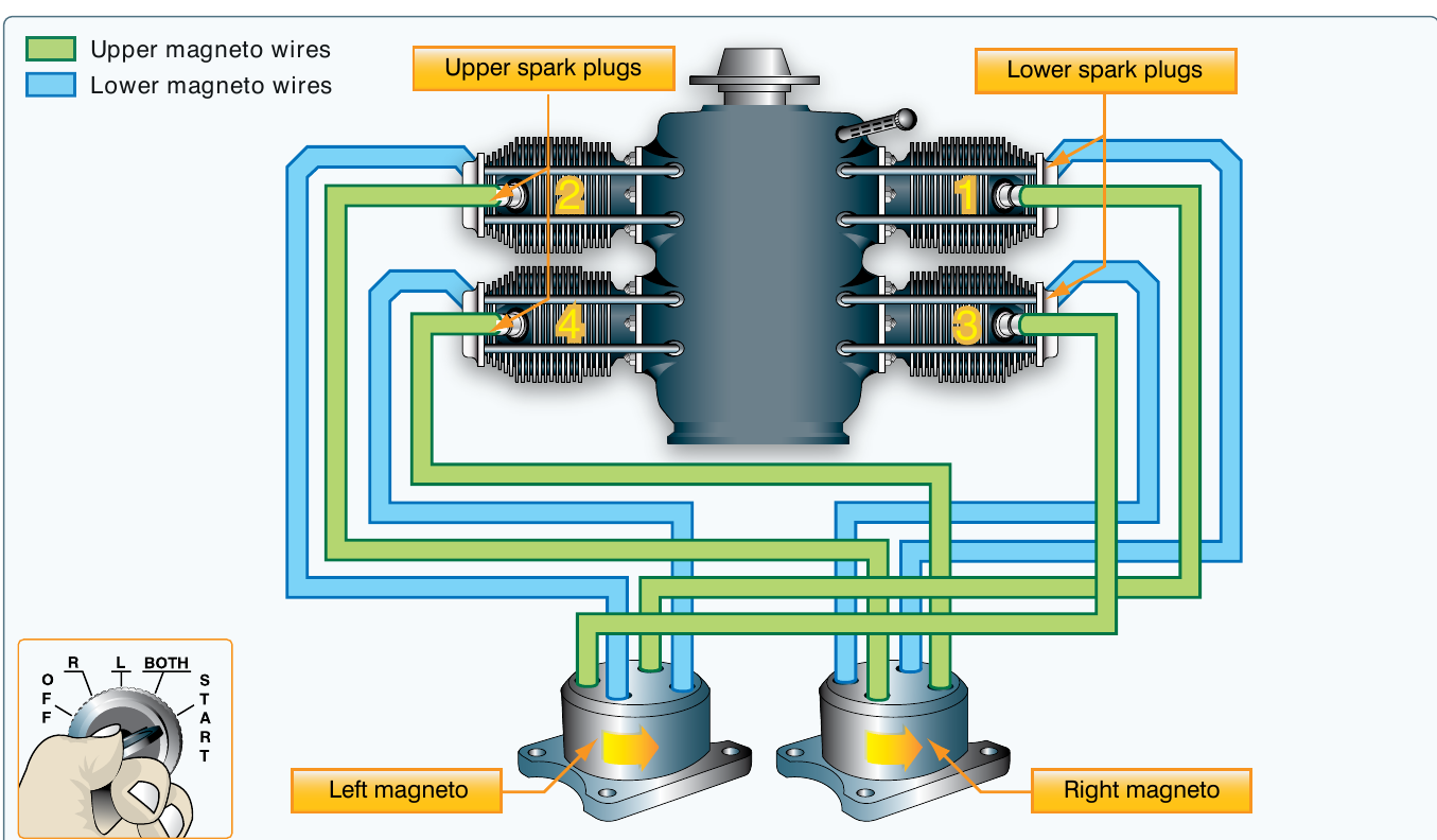
The charge in each cylinder is lit by a spark, and an airplane engine makes that spark in a way that does not depend on the battery. A magneto is a self-contained generator driven by the engine itself: once the engine is turning, each magneto produces its own high-voltage spark from the engine's rotation, with no electrical supply from the aircraft. This is why, as the cockpit lesson noted when it introduced the master switch and ignition switch, the engine keeps running after you turn the master switch off. The master switch powers the electrical system; it does not power the ignition.
The engine carries two magnetos, and each fires its own spark plug in every cylinder, so every cylinder has two plugs fed by two independent ignition systems. Two magnetos serve two purposes. The first is redundancy: if one magneto or one set of plugs fails, the engine keeps running on the other. The second is more complete combustion, because lighting the charge from two points at once burns it faster and more thoroughly than a single spark, which yields slightly more power and smoother running. During the runup before takeoff you check each magneto in turn with the ignition switch: a small RPM drop on each is normal and confirms both systems work, while no drop or an excessive one is a defect to resolve before flight.
PHAK Ch 7, "Ignition System"
Detonation and preignition
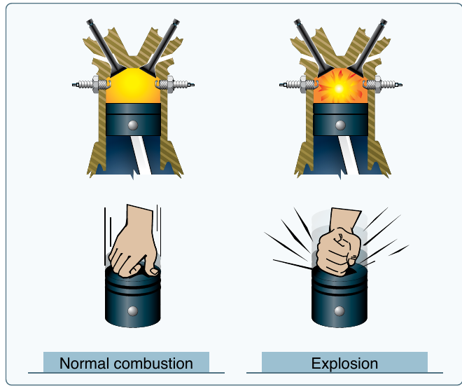
Inside the cylinder the charge is meant to burn as a smooth, fast flame front spreading from the spark plugs. Two abnormal kinds of combustion break that pattern and can wreck an engine. Detonation is the uncontrolled, explosive combustion of the charge instead of a controlled burn. It happens when the charge gets too hot or too highly pressured, or when the fuel grade is too low for the engine, and it can be brought on by an over-lean mixture at high power, an overheated engine, or climbing at too steep an angle with too little cooling airflow. The explosion spikes cylinder pressure and temperature and can hammer the pistons and other parts apart.
Preignition is the charge igniting before the spark plug fires, lit by a local hot spot such as a glowing carbon deposit or a cracked spark plug. The early, mistimed burn opposes the piston still rising on compression and overheats the cylinder, and it often sets off detonation as well. Both faults come down to excessive heat, pressure, or the wrong fuel, and the pilot prevents both the same way: use the fuel grade specified for the engine, keep the mixture and cowl-cooling airflow correct for the power setting, and watch the cylinder-head and oil temperatures rather than let them climb unchecked.
PHAK Ch 7, "Detonation" and "Preignition"
Oil and cooling
Combustion leaves the engine with more heat than it can turn into power, and two systems carry that heat away. The oil system comes first. A trainer uses a wet-sump system, meaning the oil supply sits in a reservoir at the bottom of the engine, where an engine-driven pump circulates it. The oil does four jobs at once: it lubricates the moving parts so metal does not grind on metal, it carries heat away from the hot internal parts, it seals the small gaps between the pistons and cylinder walls, and it cleans the engine by picking up debris and carrying it to the filter. You watch the oil through two gauges. The oil pressure gauge confirms the pump is moving oil through the engine, and the oil temperature gauge confirms the oil is neither too cold to flow nor too hot to protect. You also read the actual oil quantity on the dipstick during the preflight inspection.
The oil cannot absorb all the heat, so the rest goes to the air. The trainer's engine is air-cooled: baffles and seals inside the cowling force the cooling air that enters the front to flow down and around the finned cylinders, where it carries heat away before leaving through an opening at the rear. The cowling is not just a streamlined cover; it is part of the cooling system, which is one reason it stays closed and secured in flight. Engine cooling depends on airflow, so the conditions that reduce airflow while demanding high power, such as a prolonged full-power climb at low airspeed, are the ones that overheat an engine.
PHAK Ch 7, "Oil Systems" and "Engine Cooling Systems"
Check your understanding
Answer from memory, without scrolling back up. Recalling it yourself is what makes it stick.
The four strokes of the cycle occur in what order?
The cylinder draws in the charge, compresses it, burns it on the power stroke, then pushes the gases out. One power stroke comes per two crankshaft turns. (PHAK Ch 7)
The order is intake, compression, power, exhaust. The charge must be drawn in and compressed before it can be burned and then expelled.
Why is a propeller blade twisted from hub to tip?
A point near the tip moves through the air faster than one near the hub, so the blade angle decreases toward the tip to hold a useful angle of attack along the blade. (PHAK Ch 7)
The twist exists because the tip moves faster than the root. Decreasing blade angle toward the tip keeps the whole blade at a useful angle of attack.
On a fixed-pitch airplane, which gauge shows engine power?
With the blade angle fixed, RPM tracks how hard the engine works, so the tachometer is the power instrument. Manifold pressure is added on constant-speed installations. (PHAK Ch 7)
The tachometer is the power instrument on a fixed-pitch airplane. The manifold pressure gauge is added when a constant-speed propeller is fitted.
Carburetor ice is most likely in which conditions?
Ice is most likely below about 70 degrees Fahrenheit with humidity above 80 percent, though it can form on warmer humid days too. Dry air lacks the moisture to freeze. (PHAK Ch 7)
Carburetor ice needs moisture, so it favors humid air below about 70 degrees. Dry air, hot or cold, does not supply the water to freeze in the venturi.
Applying carburetor heat to an iced engine makes the RPM do what?
The warm, less dense air and the melting ice first sag the RPM, then it recovers above where it had drooped once the ice is gone. That sequence confirms ice was present. (PHAK Ch 7)
Expect a brief further drop, then a recovery above the sagging RPM as the ice melts and clears. The dip followed by a rise is the confirmation.
Why does the engine keep running with the master switch off?
Each magneto is an engine-driven generator producing its own high-voltage spark, independent of the aircraft electrical system. The master switch powers electrics, not ignition. (PHAK Ch 7)
Ignition comes from the magnetos, which make spark from the engine's rotation. Neither the battery nor the alternator is needed to keep the engine running.
The two magnetos on the engine provide what?
If one fails the other keeps the engine running, and lighting the charge from two plugs burns it faster and more thoroughly for slightly more power. (PHAK Ch 7)
Two magnetos give redundancy plus more complete combustion. They do not charge the battery, and they do not set the mixture.
Why must the mixture be leaned as altitude increases?
The carburetor keeps metering fuel for sea-level air, but the air thins with altitude, so the mixture grows too rich until the pilot leans it to restore the ratio. (PHAK Ch 7)
As air thins with altitude the fixed fuel flow makes the mixture too rich, not too lean. Leaning cuts the fuel to match the thinner air.
Detonation can be brought on by which of these?
Detonation is explosive combustion from excessive heat or pressure, or fuel of too low a grade. Using the specified fuel and managing temperature and mixture prevents it. (PHAK Ch 7)
Too low a fuel grade, an overheated engine, or an over-lean high-power mixture invite detonation. Oil grade and a rich idle are not the cause.
Falling oil pressure with rising oil temperature signals what?
Read the gauges as a pair: pressure dropping while temperature climbs points to lost oil or a failed pump and warns of engine damage. Land at the nearest suitable airport. (PHAK Ch 7)
Pressure down and temperature up together is not a normal warmup and has nothing to do with the carburetor. It warns of oil loss or pump failure.
Go deeper (primary source): read the "Reciprocating Engines," "Propeller," "Induction Systems," "Ignition System," and "Oil Systems" sections of PHAK Chapter 7. The fuel, electrical, and cabin-heat systems continue in the next lesson, Fuel, Electrical, and Other Systems.