Private Pilot · Unit 2 · 30 min
Load Factor and Turns
By the end of this lesson you will know:
- what load factor is and why it is 1G in steady, level flight
- why banking into a turn increases load factor
- how load factor raises the stall speed by its square root
- what the limit load factor and maneuvering speed protect against
- what the Vg diagram shows about the airplane's structural limits
- how bank angle and airspeed set a turn's rate and radius
What load factor is
Load factor is the ratio of the lift the wings are producing to the weight of the airplane, and it is spoken of in Gs. In steady, wings-level flight the wings carry exactly the airplane's weight, so the load factor is 1G. Pull 2 Gs and the wings are making twice the lift they need to hold the airplane up, the structure carries twice the airplane's weight, and you feel twice your own weight pressing into the seat. Load factor is the number behind that pressure, and it climbs the moment you do anything other than fly straight and level.
PHAK Ch 5, "Loads and Load Factors"
Why a turn creates load factor
Load factor in a turn is a consequence of the fact that lift is a force. In The Four Forces of Flight you saw that a force is a vector: it has a magnitude and a direction, drawn as an arrow. You also saw that any vector can be decomposed, split into two perpendicular arrows that add up to it, one vertical and one horizontal. Lift acts perpendicular to the relative wind, and in steady, wings-level flight the relative wind streams horizontally past the airplane, so the lift arrow points straight up and only has to balance weight.
Roll into a bank and the airplane tilts, lift vector included: lift remains perpendicular to the relative wind, but it now leans toward the inside of the turn instead of pointing straight up. Decompose that tilted arrow the way the vectors section showed, and the single lift force resolves into two components doing two different jobs: a vertical component still pointing up, and a horizontal component pointing toward the inside of the turn. The lift did not split into two forces; it is one force, and these are the two directions it is now pulling in at once.
The vertical component of lift still has to hold the airplane up against weight, while the horizontal component pulls the airplane around the turn. Because the vertical component must stay equal to weight to hold altitude, the total lift has to grow to cover the horizontal component on top of it. That larger total lift is the load factor climbing above 1G.
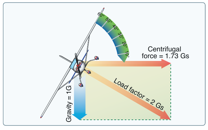
The steeper the bank, the larger the horizontal component the wing has to supply, and the more total lift it takes to keep the vertical component equal to weight. So load factor grows with bank angle, and it does not grow evenly.
Load factor rises steeply with bank
Up to about 45 degrees of bank the load factor climbs gently. Past that it rises fast. At 30 degrees it is about 1.15 Gs; at 45 degrees about 1.41 Gs; at 60 degrees it reaches 2 Gs, where the wings carry twice the airplane's weight; and at 80 degrees it is 5.76 Gs. The curve never reaches 90 degrees, because a truly 90-degree-banked turn cannot hold altitude at all.
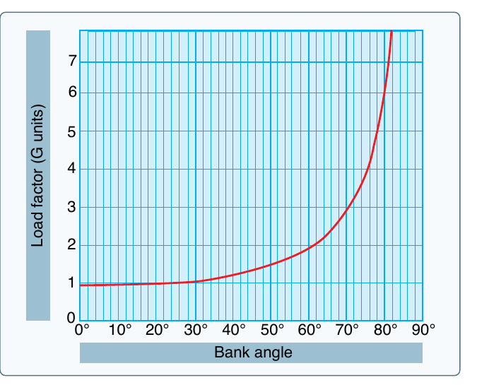
For a typical general aviation airplane, about 60 degrees of bank is the practical limit for a coordinated level turn, because holding altitude there already demands close to full power. Every additional 10 degrees of bank beyond that adds roughly another G, climbing quickly toward the airplane's structural limits.
PHAK Ch 5, "Load Factors in Steep Turns"
Load factor and stall speed
Load factor connects directly back to Stalls and Spins. Because lift grows with the square of airspeed, the airspeed at which the wing reaches its critical angle, the stall speed, rises with the square root of the load factor. Double the load and the stall speed goes up by the square root of two, about 41 percent.
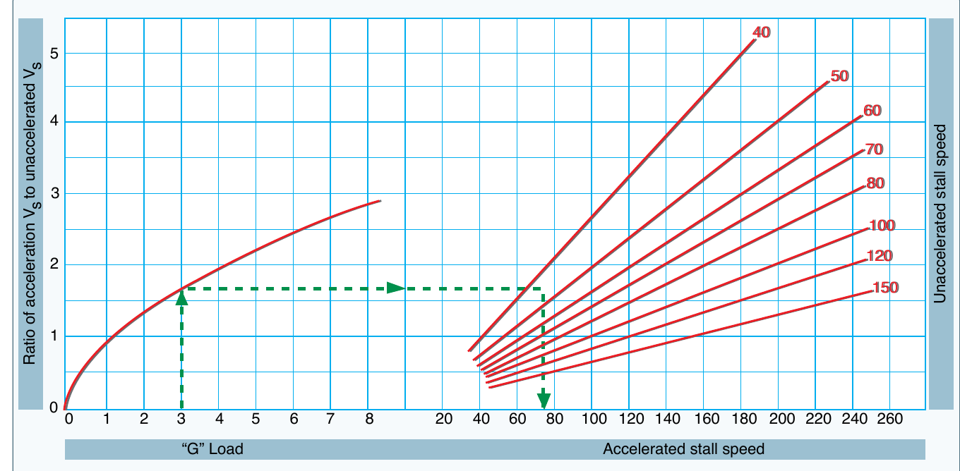
In practice, a wing can be stalled at any airspeed if you pull hard enough. An airplane that stalls at 50 knots wings-level will stall at 100 knots if you pull 4 Gs. This is the accelerated stall the stalls lesson named, now with numbers behind it. In a 60-degree-bank level turn at 2 Gs, the stall speed is already about 41 percent higher than the number in the handbook, and a steeper turn raises it further.
PHAK Ch 5, "Load Factors and Stalling Speeds"
Load factor and structure: the limit load and maneuvering speed
The other thing load factor threatens is the airframe. Every airplane is designed to a limit load factor, the most G it can take without bending something permanently. Beyond it lies the ultimate load, where the structure actually fails; certification requires a 50 percent margin between the two. Airplanes are certified in categories by how much they can take: normal category to 3.8 Gs, utility to 4.4 Gs, and acrobatic to 6.0 Gs, each with a negative limit as well.
You are kept clear of those limits by an airspeed: the maneuvering speed, or VA. Below VA, a full, abrupt deflection of a single control makes the wing stall before the load factor can build past the limit load, so the wing gives way harmlessly instead of the structure. Above VA, that same input can overstress the airplane. Two things about VA matter in the cockpit. It is lower at lighter weights, so a lightly loaded airplane has a lower maneuvering speed. And it protects against a single full input on one axis, not against repeated, combined, or reversing control inputs, which can break an airplane even below VA. So in turbulence, or before any abrupt maneuvering, slow to VA.
PHAK Ch 5, "Load Factors and Flight Maneuvers"
The Vg diagram
All of this fits on a single chart of the airplane's flight envelope, called the Vg diagram: airspeed along the bottom, load factor up the side. It shows every combination of speed and G the airplane can survive.

Each boundary on the diagram carries a specific meaning. The curved lines on the left are the maximum lift the wing can make: fly to the left of them and the wing stalls, so no higher load factor is available there. The horizontal lines top and bottom are the limit load factors, the structural ceiling and floor. Where the stall line meets the top limit-load line is the maneuvering speed: below it the airplane stalls before it can be overstressed, above it the structure is at risk. The right edge is the never-exceed speed (VNE), the redline beyond which flutter or structural failure can occur. The enclosed area is the envelope, and safe flying stays inside it.
PHAK Ch 5, "Vg Diagram"
Turning: rate and radius
Because this lesson is also about turns, it is worth seeing how bank and speed set the turn itself. The rate of turn is how fast the heading changes, in degrees per second, and the radius of turn is how much ground the circle covers. Two relationships are worth carrying:
- At a given airspeed, steepening the bank turns the airplane faster and tighter: higher rate, smaller radius. It also raises the load factor, which is the price of the tighter turn.
- At a given bank angle, flying faster turns the airplane slower and wider: lower rate, larger radius. This is why fast airplanes need a lot of room to come around.
One rate has a name you will use constantly once you fly on instruments: the standard-rate turn, 3 degrees per second, which takes two minutes to go all the way around. Holding a standard rate takes more bank as you fly faster, which is one more place the speed-and-bank relationship shows up.
PHAK Ch 5, "Rate of Turn" and "Radius of Turn"
Check your understanding
Answer from memory, without scrolling back up. Recalling it yourself is what makes it stick.
Load factor is the ratio of?
Load factor is lift over weight, expressed in Gs. It is 1G in level flight and climbs whenever the wing makes more lift than the airplane's weight. (PHAK Ch 5)
Load factor compares lift to weight. At 2 Gs the wings make twice the lift needed to hold the airplane up, and you feel twice your weight.
To hold altitude in a level banked turn, total lift must be?
In a bank, lift also has to pull the airplane around the turn, so total lift must grow to keep its vertical component equal to weight. That extra lift is load factor. (PHAK Ch 5)
Lift tilts in a bank and takes on a horizontal component, so the total must exceed weight to keep the vertical component holding altitude.
The load factor in a 60-degree-bank level turn is about?
At 60 degrees of bank a level turn pulls 2 Gs, and this is near the practical limit for a typical general aviation airplane. (PHAK Ch 5)
A 60-degree level turn is 2 Gs. The curve is gentle to 45 degrees, then climbs fast toward the structural limits.
As load factor increases, the stall speed rises with the?
Stall speed grows with the square root of load factor, because lift grows with the square of airspeed. At 2 Gs, stall speed is about 41 percent higher. (PHAK Ch 5)
It is the square root, not the square. Pulling 4 Gs raises the stall speed by the square root of four, so it doubles.
A wing that stalls at 50 knots level will, at 4 Gs, stall near?
The multiplier is the square root of the load factor: the square root of four is two, so 50 knots becomes about 100. (PHAK Ch 5)
At 4 Gs the stall speed doubles, to about 100 knots, because it scales with the square root of load factor.
Below maneuvering speed, an abrupt full control input makes the?
Below V-A the wing reaches its critical angle and stalls before the load factor can exceed the limit load, so the wing gives way instead of the airframe. (PHAK Ch 5)
The point of V-A is that the wing stalls first below it, relieving the load before the structure is overstressed.
As the airplane's weight decreases, maneuvering speed?
V-A is lower at lighter weights. A lightly loaded airplane must slow more before abrupt inputs or rough air than a heavy one. (PHAK Ch 5)
Maneuvering speed drops with weight, so a light airplane has a lower V-A. Do not assume the heavy-weight number always applies.
The curved boundaries on a Vg diagram represent the?
The curved lines are maximum lift: to their left the wing stalls, so no higher load factor is available there. (PHAK Ch 5)
The curves are the stall limit. The redline is the right edge of the diagram, and the horizontal lines are the limit load factors.
Flying beyond the limit load factor risks?
The limit load is the most G the structure takes without bending permanently. Past it, damage begins; past the ultimate load, it fails. (PHAK Ch 5)
Exceeding the limit load deforms the airframe. It is a structural limit, not a stall or a turn-performance effect.
At a given airspeed, steepening the bank makes the turn?
More bank at the same speed means a higher rate and smaller radius, and it raises the load factor as the price. (PHAK Ch 5)
Steeper bank at a fixed speed tightens and quickens the turn, and the load factor rises with it.
Go deeper (primary source): read the "Loads and Load Factors" section of PHAK Chapter 5, including the Vg diagram and the rate and radius of turn. It carries these same figures and works several load-factor examples with numbers.